CPT7 and CPT7700 Installation and Operation User Manual v12
9
Figures
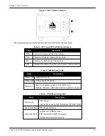
Figure 3: CPT7 Status Indicators
Figure 4: Typical Installation of a CPT7 System
Figure 5: Typical Installation of a CPT7700 System
Figure 6: Default RBV Configuration
Figure 8: Offset from the CPT7 to the SPAN-CPT
Figure 9: Offset from the CPT7 to the SPAN-IGM-S1
Figure 10: Fuse for CPT7 Power Supply
Figure 11: Dedicated Battery for the CPT7
Figure 12: Basic CPT7 Connection Interfaces (example)
Figure 13: Basic Differential Setup
Figure 14: Positioning Change Without STEADYLINE
Figure 15: STEADYLINE Prefer Accuracy
Figure 16: Transfer COARSE Time from Fine Clock to Cold Clock Receiver
Figure 17: Transfer FINE Time from Fine Clock to Cold Clock Receiver
Figure 18: Transfer FINE Time from Fine Clock to Warm Clock Receiver
Figure 20: Local-Level Frame (ENU)
Figure 21: IMU Body Frame Marking
Figure 23: IMU to Antenna Translation Offset
Figure 24: CPT7 to Antenna Offset
Figure 25: Rear View of CPT7 – Mounting Plate is not Flat
Figure 26: Side View of CPT7 – Vehicle is not Level
Figure 27: Top View of CPT7 – CPT7 Misalignment
Figure 28: Multi-Line IMU Body to Vehicle Calibration
Figure 31: Sample Configuration
Figure 33: Relative INS Example
Figure 34: SPAN – CPT7700 Dual Antenna Installation


