Chapter 4 SPAN Operation
CPT7 and CPT7700 Installation and Operation User Manual v12
80
The offset between the antenna phase center and the IMU axis must remain constant and be known
accurately (m). The X, Y and Z directions are clearly marked on the CPT7 enclosure. The
SETINSTRANSLATION parameters are (where the standard deviation fields are optional and the
distances are measured from the CPT7 to the antenna):
ANT1 x_offset y_offset z_offset [x_stdev] [y_stdev] [z_stdev]
ANT2 x_offset y_offset z_offset [x_stdev] [y_stdev] [z_stdev]
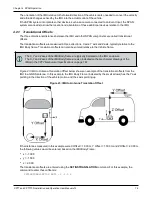
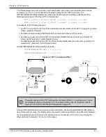
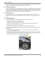
For example, in the following scenario:
l
the CPT7 is mounted on the floor in the orientation described in
on page 31 (positive
Z down, positive X forward)
l
the primary and secondary GNSS antennas are mounted on the roof of the vehicle
l
the distance measured from the CPT7 to the primary GNSS antenna is 2 meters up (Z axis), 0.5
meters right (Y axis) and 1 meter forward (X axis)
the distance measured from the CPT7 to the secondary GNSS antenna is 2 meters up (Z axis), 0.5
meters left (Y axis) and 1 meter forward (X axis)
the SETINSTRANSLATION commands would be:
SETINSTRANSLATION ANT1 1.0 -0.5 -2.0
SETINSTRANSLATION ANT2 1.0 0.5 -2.0
Figure 24: CPT7 to Antenna Offset
The axis marking on the CPT7 indicates the orientation of the X, Y and Z axis only. It does
not indicate the center of navigation. For the location of the center of navigation, refer to
Figure 51: CPT7/CPT7700 Center of Navigation
A typical RTK GNSS solution is accurate to a few centimeters. For the integrated GNSS+INS system to
have this level of accuracy, the offset must be measured to within a centimeter. Any offset error between
the two systems shows up directly in the output position. For example, a 10 cm error in recording this
offset will result in at least a 10 cm error in the output.


