Chapter 4 SPAN Operation
CPT7 and CPT7700 Installation and Operation User Manual v12
94
complete revolution of the wheel. The resulting precision will be 0.002 m/tick. Given the same wheel, but a
DMI rated for 10 ticks per revolution, the resulting precision will be 0.2 m/tick.
4.5.1 DMI Communication
The CPT7 supports single channel DMI data transmission using a pair of complementary signals represented
as A+ and A-. Differential signals resist electromagnetic (EM) noise and improve robustness in challenging
electrical environments compared to a single-ended pulse. Single channel connections provide benefit to the
SPAN solution by measuring the distance traveled without regard for direction.
4.5.2 DMI Connection
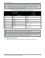
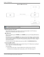
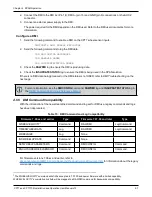
For a SPAN system with a CPT7, the DMI can be connected to the DMI input on the IO2 connector. For
information about connecting and configuring a DMI to a CPT7, see
4.5.3 DMI Requirements
The CPT7 is compatible with any wheel sensor meeting the following requirements:
l
Output signal duty cycle is symmetric 40% to 60%.
l
Output signal voltage is RS-422 compliant (differential).
l
The wheel sensor is powered externally. The receiver does not supply power to the wheel sensor.
l
Pulse and direction wheel sensors are compatible.
l
Expected maximum pulse rate over measurement range does not exceed 100,000 Hz
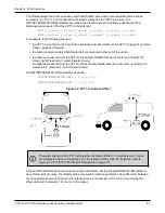
An example of a compatible DMI is the Kistler Wheel Pulse Transducer CWPTA411 (WPT). See
l
A transducer traditionally fits to the outside of a non-drive wheel. A pulse is then generated from the
transducer which is fed to the receiver.
l
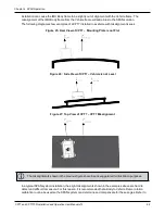
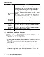
The WPT mounts to the wheel lug nuts via adjustable mounting collets. The torsion protection rod, which
maintains rotation around the wheel axis, affixes to the vehicle body with suction cups. Refer to the Kistler
WPT (part number CWPTA411) user manual for mounting instructions.
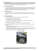
Figure 29: Kistler WPT

