CPT7 and CPT7700 Installation and Operation User Manual v12
11
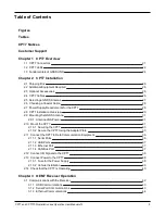
Tables
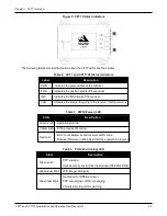
Table 2: CPT7 and CPT7700 Status Indicators
Table 4: POS (Positioning) LED
Table 6: LOG (Onboard Storage) LED
Table 8: Fuse/Holder Recommendations
Table 9: Serial Ports Supported
Table 11: Inertial Solution Status
Table 14: Kistler to NovAtel Wheel Sensor Cable Connections
Table 15: DMI Command and Log Compatibility
Table 16: Valid Event Inputs and Outputs for Timed Sensor Triggers
Table 17: Logs with Azimuth Data
Table 18: Logs used with Variable Lever Arm
Table 19: Commands used with Variable Lever Arm
Table 21: Troubleshooting Based on Symptoms
Table 22: Resolving a Receiver Error Word
Table 23: Resolving an Error in the Receiver Status Word
Table 24: Resolving an Error in the AUX1 Status Word
Table 25: CPT7 Physical Description
Table 26: CPT7 Receiver Performance
Table 27: CPT7700 Receiver Performance
Table 28: CPT7 IMU Performance
Table 29: CPT7 Environmental Specifications
Table 30: CPT7 Power Requirements
Table 31: CPT7 RF Input/LNA Power Output
Table 32: CPT7 Wheel Sensor Input Signal Levels
Table 33: Data Communications Interfaces
Table 34: CPT7 Strobes Description


