Chapter 2 CPT7 Installation
CPT7 and CPT7700 Installation and Operation User Manual v12
33
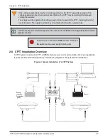
The closer the primary antenna is to the CPT7, particularly in the horizontal plane, the more accurate
the position solution.
Also, your measurements entered using the
SETINSTRANSLATION
command must be as accurate
as possible, or at least more accurate than the GNSS positions being used.
For example, a 10 cm
error in recording the antenna offset will result in at least a 10 cm error in the output.
Millimeter accuracy is preferred.
The offset from the CPT7 to the antennas, and/or a user point device, must remain constant
especially for RTK or DGNSS data. Ensure the CPT7, antenna and user point device are bolted in one
position perhaps by using a custom bracket.
2.10.1 Securing the CPT7
The CPT7 can be secured directly to the mounting surface or can be secured using the CPT7 Adapter Plate
(01020112).
To secure the CPT7 directly to the mounting surface, use four #6 screws that pass through the mounting holes
in the CPT7 and into the mounting surface. For the location and spacing of the mounting holes, refer to the
mechanical drawings in
CPT7 Mechanical Specifications
The mounting screws should be torqued to 8 to 10 in-lbs (0.9 to 1.1 Nꞏm).
For information about securing the CPT7 using the adapter plate, refer to
Secure the CPT7 Using the Adapter
2.10.2 Secure the CPT7 Using the Adapter Plate
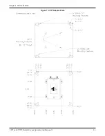
The CPT7 Adapter Plate (01020112) allows the CPT7 to be installed using the mounting hole spacing
designed for the SPAN-CPT or SPAN-IGM-A1/S1.
To secure a CPT7 using the Adapter Plate:
1. Place the CPT7 on the Adapter Plate and align the mounting holes on the CPT7 with the threaded holes in
the Adapter Plate.
2. Secure the CPT7 to the Adapter Plate using the four screws (#6 - 32) included with the mounting plate.
3. Secure the Adapter Plate to the mounting location using 4 screws.
See
on the next page for the adapter plate dimensions and mounting hole
locations.
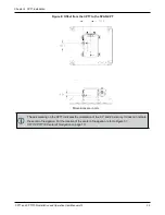
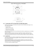
4. If the CPT7 is replacing a SPAN-CPT or SPAN-IGM-S1, see
Figure 8: Offset from the CPT7 to the SPAN-
on page 35 or
Figure 9: Offset from the CPT7 to the SPAN-IGM-S1
on page 36 for the offset of the
center of navigation of the previous system to the center of navigation of the CPT7.

