Chapter 4 SPAN Operation
CPT7 and CPT7700 Installation and Operation User Manual v12
99
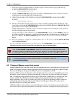
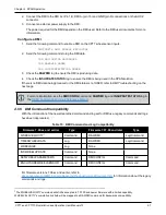
Time Guard (t_guard)
:
The time guard specifies the minimum number of milliseconds between pulses. This is used to coarsely
filter the input pulses.
The time of the input pulses is available from the
MARKTIME, MARK2TIME, MARK3TIME and MARK4TIME
log. The solution synchronous with the event pulses is available from the
MARK1PVA, MARK2PVA,
MARK3PVA and MARK4PVA
log. The logs required for input strobes are:
LOG MARK1TIMEB ONNEW
Output time for every pulse received.
LOG MARK1PVAB ONNEW
Output time, position, velocity and attitude for every pulse received at the location specified by the
SETINSTRANSLATION
command and
SETINSROTATION
command.
The above example is for the MARK1 event input. The minimum detectable pulse duration must be greater
than or equal to 1 microsecond.
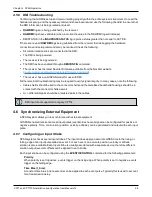
The input signal levels are 3.3 V to 0 V. Signal voltages outside these bounds damage the receiver.
For information about the logs and commands used in this procedure, refer to the
.
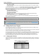
4.7 Adding Timed Sensor Triggers
Use the EVENT IN and EVENT OUT connections to attach up to three sensor devices to an OEM7 receiver
and then trigger the sensors based upon GPS time.
In this context a 'sensor' is any external device. The 'sensor' reference in the receiver is an object consisting of
an Event_In and Event_Out pair of system strobes all linked by a sensor identifier.
You can send multiple trigger events marked with a user-specified ID and a GPS time to trigger the sensor. At
the requested trigger time, the receiver outputs a user-specified LVCMOS level pulse to the sensor and waits
for a response pulse to indicate a sensor measurement (i.e. camera exposure). When this response is
received, the SPAN system outputs a log with the inertial position/velocity/attitude and the ID of the event.
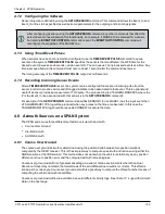
4.7.1 Configuring the Hardware
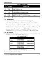
A sensor's trigger input is connected to a valid Event_Out and the sensor’s response output is connected to a
valid Event_In. Three sensor slots are available for use, but may be limited to less depending on the hardware
platform used.
Valid Event Outputs
Valid Event Inputs
MARK1
MARK1
MARK2
MARK2
MARK3
MARK3
Table 16: Valid Event Inputs and Outputs
for Timed Sensor Triggers

