Chapter 2 CPT7 Installation
CPT7 and CPT7700 Installation and Operation User Manual v12
37
1. Connect the CPT7 I/O2 cable, or a custom made cable, to the IO2 connector.
2. Connect the DB9 female connector on the cable to the serial port on the computer or other data
communication device.
To connect to a serial port using RS-422 protocol:
1. Connect the CPT7 I/O1 cable, or a custom made cable, to the IO1 connector.
2. Connect the DB9 female connector on the cable to the serial port on the computer or other data
communication device.
2.11.2 USB Ports
The CPT7 has one USB 2.0 compatible port available on the IO2 connector. This USB port operates at 480
Mb/s.
To connect to the USB port:
1. Connect the CPT7 I/O2 cable, or a custom made cable, to the IO2 connector.
2. Connect the USB connector on the CPT7 I/O2 cable to a USB port on the computer or other data com-
munication device.
2.11.3 Ethernet Port
The CPT7 has a 10Base-T/100Base-TX Ethernet on the IO2 connector that can be used for communications
with external data communications equipment such as computers and data loggers. The Ethernet port
supports IPv4 Internet layer, TCP/IP transport, ping and connection from a Telnet client. Users can conduct
remote debugging, accept MRTCA (modified RTCA) data and download firmware. OEM7 receivers are also
equipped with NTRIP Version 2.0 (Networked Transport of RTCM via Internet Protocol) client and server
capability.
To connect to the Ethernet port:
1. Connect the CPT7 I/O2 cable, or a custom made cable, to the IO2 connector.
2. Connect an Ethernet cable from the RJ45 jack on the CPT7 I/O2 cable to an Ethernet port on the com-
puter or other data communication device.
Refer to
on page 114 for instructions on configuring Ethernet and NTRIP.
2.11.4 CAN Bus Port
The CPT7 has a CAN Bus port available on the IO2 connector.
To connect to the CAN Bus port:
1. Connect the CPT7 I/O2 cable, or a custom made cable, to the IO2 connector.
2. Connect the CAN signals, available on the DB15 connector, to the CAN Bus.
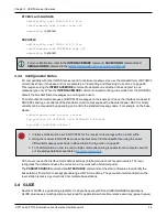
The CPT7 CAN bus port is unterminated. If the CPT7 is at the end of the bus, then the connecting
cable must have 120 Ω of resistance integrated into the cable between CANH and CANL in close
proximity to the I/O2 connector.
For information about configuring CAN, see

