Upgrading Your System 4-9
4.
Remove the five screws securing the hard disk drive cage(s) to the front of
the chassis. Save the screws for reinstallation.
5.
Pull the hard disk drive cage(s) out the front of the chassis approximately
one inch (5 cm).
6.
Remove the fan cover. See
Removing the Fan Cover
earlier in this chapter.
7.
Tag and disconnect the two cooling fan cable connectors from their mating
connectors on the system board.
8.
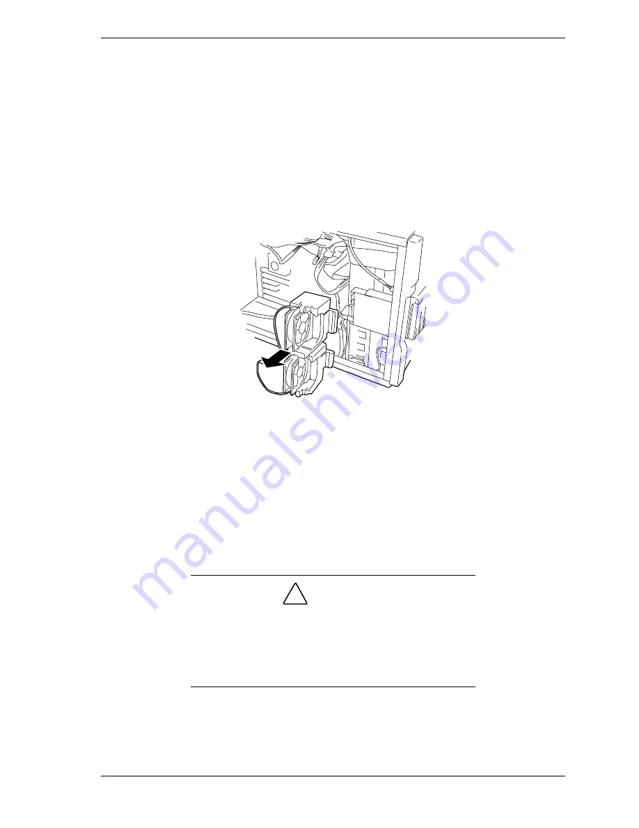
Grasp and pull the fan module out the side of the chassis and remove it. See
Figure 4-7.
Figure 4-7. Removing the Fan Module
Installing the Fan Module
To
install
the fan module, perform the following procedures:
1.
Make sure all option boards are firmly seated in their respective slots and
that all interior cables are properly connected.
2.
Reconnect the two cooling fan cable connectors to their mating connectors
on the system board.
!
CAUTION
Always make sure that you connect the fan cable connectors
to their specific cable connectors on the system board. If the
fan cable connectors are not connected to their specific
cable connectors on the system board the fans will not
operate. This may cause a rise in chassis temperature and a
malfunction to occur.
Summary of Contents for EXPRESS5800/120Lf
Page 1: ... U s e r s G u i d e EXPRESS5800 120Lf ...
Page 2: ...NEC ...
Page 3: ... U s e r s G u i d e EXPRESS5800 120Lf ...
Page 9: ...Contents vii ...
Page 10: ...viii Contents ...
Page 36: ...1 20 System Overview ...
Page 99: ...Upgrading Your System 4 13 Figure 4 9 Replacing the Real Time Clock Battery ...
Page 146: ...4 60 Upgrading Your System Figure 4 60 Installing a Power Supply ...
Page 170: ...5 24 Problem Solving ...
Page 171: ...A Technical Specifications Server Unit ...
Page 174: ...A 4 Technical Specifications ...
Page 175: ...B Connectors Overview External Device Connector Pin Information ...
Page 190: ...10 Glossary ...
Page 196: ...Index 4 ...
Page 197: ...xx ...
Page 198: ... 456 01575 N00 ...


