Upgrading Your System 4-39
6.
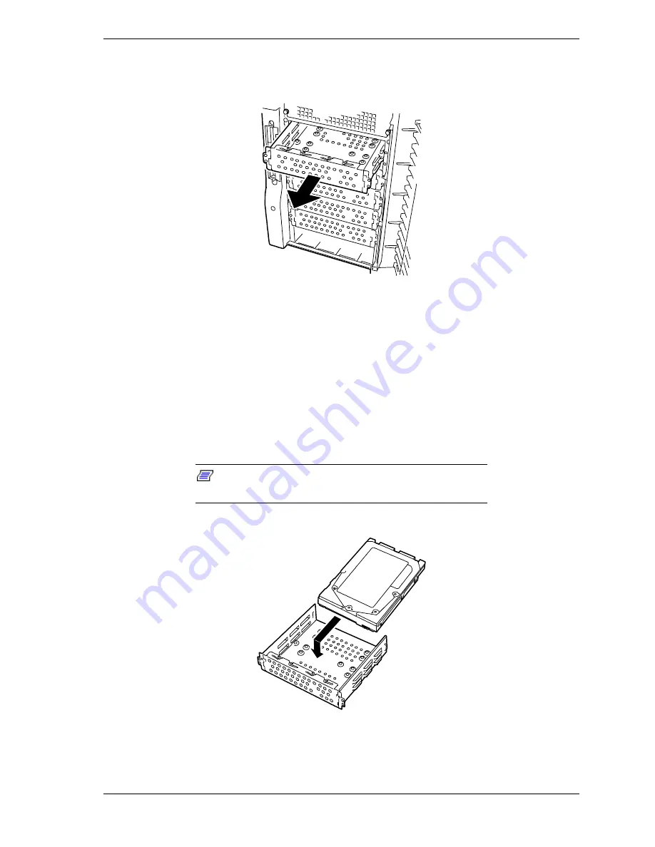
Slide the disk carrier tray out the front of the chassis. See Figure 4-36. Save
the disk carrier tray and screws for reinstallation.
Figure 4-36. Removing the Disk Carrier Tray
7.
Remove the device from its protective wrapper and place it on an antistatic
surface. Record the drive model and serial number in the equipment log.
8.
Set any drive jumpers or switches before you install the drive. See the
documentation that comes with the device for jumper or switch information.
9.
Place the drive into the disk carrier tray removed in steps 5 and 6 above.
Make sure the drives component side down and with the power and data
connectors facing the rear of the carrier. The connectors should be flush with
the rear of the carrier. See Figure 4-37.
Note:
If the drive comes with drive rails, do not use
them. Remove any rails already attached.
Figure 4-37. Placing the Hard Drive into a Disk Carrier Tray
Summary of Contents for EXPRESS5800/120Lf
Page 1: ... U s e r s G u i d e EXPRESS5800 120Lf ...
Page 2: ...NEC ...
Page 3: ... U s e r s G u i d e EXPRESS5800 120Lf ...
Page 9: ...Contents vii ...
Page 10: ...viii Contents ...
Page 36: ...1 20 System Overview ...
Page 99: ...Upgrading Your System 4 13 Figure 4 9 Replacing the Real Time Clock Battery ...
Page 146: ...4 60 Upgrading Your System Figure 4 60 Installing a Power Supply ...
Page 170: ...5 24 Problem Solving ...
Page 171: ...A Technical Specifications Server Unit ...
Page 174: ...A 4 Technical Specifications ...
Page 175: ...B Connectors Overview External Device Connector Pin Information ...
Page 190: ...10 Glossary ...
Page 196: ...Index 4 ...
Page 197: ...xx ...
Page 198: ... 456 01575 N00 ...


