Setting Up the System 2-7
4.
With each slide rail assembly on a flat surface loosen the screws that attach
their outer and inner brackets together. Set the slide rail assemblies aside for
installation into the rack cabinet.
5.
Each slide rail assembly can be separated and adjusted. The distance
between its front rack mounting bracket and its rear rack mounting bracket is
adjustable to fit between the front and rear vertical rails of the system rack.
6.
Select an appropriate location in the rack cabinet for the rack-mount server.
To improve rack stability, mount heavier items towards the bottom of the
rack cabinet.
Note:
When planning the server configuration for the
rack cabinet you should consider the length of the cables
that interconnect with system components.
Attaching the Rail Assembly Mounting Brackets to the Rack
Cabinet
1.
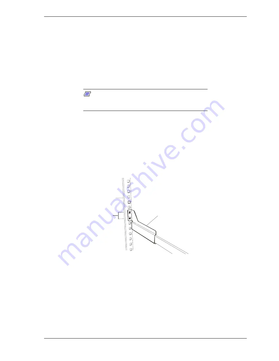
Attach the left side front and rear mounting brackets to the rack cabinet
using two Phillips flange head screws supplied. See Figure 2-3.
2.
Attach the right side front and rear mounting brackets to the rack cabinet
using two Phillips flange head screws supplied.
A
B
C
A
Rack
B
Rail assembly
C
Mounting holes
Figure 2-3. Attaching the Mounting Brackets to the Rack Cabinet
3.
Adjust and tighten the screws that attach the outer and inner brackets of each
slide rail assembly together.
4.
Securely tighten all the Phillips screws installed in steps 1 through 2 above.
Summary of Contents for EXPRESS5800/120Lf
Page 1: ... U s e r s G u i d e EXPRESS5800 120Lf ...
Page 2: ...NEC ...
Page 3: ... U s e r s G u i d e EXPRESS5800 120Lf ...
Page 9: ...Contents vii ...
Page 10: ...viii Contents ...
Page 36: ...1 20 System Overview ...
Page 99: ...Upgrading Your System 4 13 Figure 4 9 Replacing the Real Time Clock Battery ...
Page 146: ...4 60 Upgrading Your System Figure 4 60 Installing a Power Supply ...
Page 170: ...5 24 Problem Solving ...
Page 171: ...A Technical Specifications Server Unit ...
Page 174: ...A 4 Technical Specifications ...
Page 175: ...B Connectors Overview External Device Connector Pin Information ...
Page 190: ...10 Glossary ...
Page 196: ...Index 4 ...
Page 197: ...xx ...
Page 198: ... 456 01575 N00 ...


