6-7
6.4 PCL printer controller
6.4.1 Packaging contents:
1. PCL printer board ............................................ 1
2. Spacers ........................................................... 2
3. Screw .............................................................. 2
4. CD .................................................................. 1
Note:
Two screws are included, but only one is required to for installation.
6.4.2 Installation
1. Turn the power off and unplug the power cord.
2. Remove the covers.
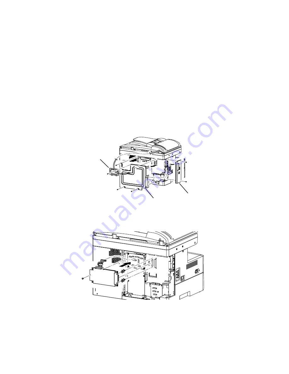
1) Remove the connect cover screw and the cover.
2) Unplug the harness that is going through the connect cover.
3) Remove the two screws and the option cover.
4) Remove the five screws and the shield cover.
Connect cover
Shield cover
Option cover
3. Attach two spacers to the Main PCB.
4. Attach the PCL printer board to the machine and connect the cable to the P82 connector.
5. Attach the left side of the PCL printer board using one screw.
6. Reattach the shield cover and the option cover.
7. Connect the ADF cable to the connector on the PCB bracket.
8. Reattach the connect cover.
*Use the enclosed CD to install the print drivers.
Summary of Contents for F-525
Page 65: ...2 12 2 4 Interconnect Block Diagram See the attached files...
Page 188: ...3 104 3 8 3 How to see the print out Example for fax transmission...
Page 252: ...3 168 6 Click OK 7 Click Next The driver will be installed on the PC...
Page 253: ...3 169 8 Click Finish and finish the Found New Hardware Wizard...
Page 263: ...3 179...
Page 264: ...3 180...
Page 353: ...5 63 6 Remove one bearing and slide out the ROLLER FEED DUPLEX ROLELR FFED DUPLEX...
Page 382: ......
Page 383: ......


