i
Table of Contents
Chapter 1
MODEL OVERVIEW
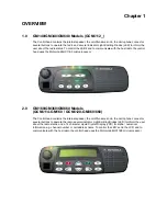
1.0 GM140/GM340/GM640 Models ...........................................................................1-1
2.0 GM160/GM360/GM660 Models ...........................................................................1-1
3.0 GM380/GM1280 Models......................................................................................1-2
Chapter 2
THEORY OF OPERATION
1.0 Introduction ..........................................................................................................2-1
2.0 Controlhead Model for GM140, GM340 and GM640 ...........................................2-1
2.1 Power Supplies...............................................................................................2-1
2.2 Power On / Off................................................................................................2-1
2.3 Microprocessor Circuit....................................................................................2-1
2.4 SBEP Serial Interface.....................................................................................2-2
2.5 Keypad Keys ..................................................................................................2-2
2.6 Status LED and Back Light Circuit..................................................................2-3
2.7 Microphone Connector Signals ......................................................................2-3
2.8 Speaker ..........................................................................................................2-4
2.9 Electrostatic Transient Protection ...................................................................2-4
3.0 Controlhead Model for GM160, GM360 and GM660 ...........................................2-4
3.1 Power Supplies...............................................................................................2-4
3.2 Power On / Off................................................................................................2-4
3.3 Microprocessor Circuit....................................................................................2-5
3.4 SBEP Serial Interface.....................................................................................2-5
3.5 Keypad Keys ..................................................................................................2-6
3.6 Status LED and Back Light Circuit..................................................................2-6
3.7 Liquid Crystal Display (LCD) ..........................................................................2-6
3.8 Microphone Connector Signals ......................................................................2-7
3.9 Speaker ..........................................................................................................2-8
3.10 Electrostatic Transient Protection ...................................................................2-8
4.0 Controlhead Model for GM380 and GM1280.......................................................2-8
4.1 Power Supplies...............................................................................................2-8
4.2 Voltage Regulator Circuit................................................................................2-8
4.3 Power On / Off................................................................................................2-9
4.4 Microprocessor Circuit....................................................................................2-9
4.5 SBEP Serial Interface.....................................................................................2-9
4.6 Keypad Keys ................................................................................................2-10
4.7 Status LED and Back Light Circuit................................................................2-10
4.8 Liquid Crystal Display (LCD) ........................................................................2-11
4.9 Microphone Connector Signals ....................................................................2-11
4.10 Speaker ........................................................................................................2-12
4.11 Electrostatic Transient Protection .................................................................2-12
Summary of Contents for 6864115B62-C
Page 1: ...Professional Radio GM Series Detailed Service Manual 6864115B62 C ...
Page 2: ...ii ...
Page 4: ...iv ...
Page 5: ...Professional Radio GM Series Service Maintainability Issue July 2007 ...
Page 8: ...ii ...
Page 22: ...2 10 MAINTENANCE ...
Page 25: ...Professional Radio GM Series Controlhead Service Information Issue July 2007 ...
Page 77: ...Professional Radio GM Series Controller Service Information Issue May 2007 ...
Page 100: ...2 2 TROUBLESHOOTING CHARTS ...
Page 104: ...3 4 Controller schematics parts list ...
Page 154: ...3 52 Controller T12 Schematic Diagrams ...
Page 155: ...Professional Radio GM Series VHF 136 174MHz Service Information Issue May 2007 ...
Page 164: ...1 6 MODEL CHART AND TECHNICAL SPECIFICATIONS ...
Page 176: ...2 12 THEORY OF OPERATION ...
Page 186: ...3 10 TROUBLESHOOTING CHARTS ...
Page 190: ...4 4 VHF PCB SCHEMATICS PARTS LISTS ...
Page 252: ...4 66 VHF 1 25W PCB 8471235L02 Schematics VHF 136 174 MHz IF ...
Page 256: ...4 70 VHF 1 25W PCB 8471235L02 Schematics ...
Page 257: ...Professional Radio GM Series UHF 403 470MHz Service Information Issue May 2007 ...
Page 266: ...1 6 MODEL CHART AND TECHNICAL SPECIFICATIONS ...
Page 366: ...2 12 THEORY OF OPERATION ...
Page 372: ...3 6 Low Band TROUBLESHOOTING CHARTS ...


