


2-12
THEORY OF OPERATION
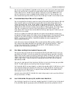
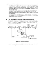
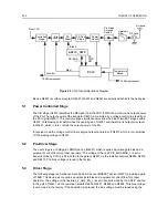
programmed at several points across the frequency range of the transmitter to offset frequency
response variations of the transmitter’s power detector circuitry.
The PCIC provides a DC output voltage at pin 4 (INT) which is applied as CNTLVLTG to the power-
adjust input pin of the first transmitter stage U4401. This adjusts the transmitter power output to the
intended value. Variations in forward transmitter power cause the DC voltage at pin 1 to change,
and the PCIC adjusts the control voltage above or below its nominal value to raise or lower output
power.
Capacitors C4502-4, in conjunction with resistors and integrators within the PCIC, control the
transmitter power-rise (key-up) and power-decay (de-key) characteristic to minimize splatter into
adjacent channels.
U4502 is a temperature-sensing device, which monitors the circuit board temperature in the vicinity
of the transmitter driver and final devices, and provides a dc voltage to the PCIC (TEMP, pin 29)
proportional to temperature. If the DC voltage produced exceeds the set threshold in the PCIC, the
transmitter output power will be reduced so as to reduce the transmitter temperature.
Summary of Contents for 6864115B62-C
Page 1: ...Professional Radio GM Series Detailed Service Manual 6864115B62 C ...
Page 2: ...ii ...
Page 4: ...iv ...
Page 5: ...Professional Radio GM Series Service Maintainability Issue July 2007 ...
Page 8: ...ii ...
Page 22: ...2 10 MAINTENANCE ...
Page 25: ...Professional Radio GM Series Controlhead Service Information Issue July 2007 ...
Page 77: ...Professional Radio GM Series Controller Service Information Issue May 2007 ...
Page 100: ...2 2 TROUBLESHOOTING CHARTS ...
Page 104: ...3 4 Controller schematics parts list ...
Page 154: ...3 52 Controller T12 Schematic Diagrams ...
Page 155: ...Professional Radio GM Series VHF 136 174MHz Service Information Issue May 2007 ...
Page 164: ...1 6 MODEL CHART AND TECHNICAL SPECIFICATIONS ...
Page 176: ...2 12 THEORY OF OPERATION ...
Page 186: ...3 10 TROUBLESHOOTING CHARTS ...
Page 190: ...4 4 VHF PCB SCHEMATICS PARTS LISTS ...
Page 252: ...4 66 VHF 1 25W PCB 8471235L02 Schematics VHF 136 174 MHz IF ...
Page 256: ...4 70 VHF 1 25W PCB 8471235L02 Schematics ...
Page 257: ...Professional Radio GM Series UHF 403 470MHz Service Information Issue May 2007 ...
Page 266: ...1 6 MODEL CHART AND TECHNICAL SPECIFICATIONS ...
Page 366: ...2 12 THEORY OF OPERATION ...
Page 372: ...3 6 Low Band TROUBLESHOOTING CHARTS ...