1-2
INTRODUCTION
2.3
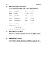
European Radio Support Centre (ERSC)
The ERSC Customer Information Desk is available through the following service numbers:
Austria:
06 60 75 41
Italy:
16 78 77 387
Belgium:
08 00 72 471
Luxemburg:
08 00 23 27
Denmark:
80 01 55 72
Netherlands:
60 22 45 13
Finland:
08 00 11 49 10
Norway:
80 01 11 15
France:
05 90 30 90
Portugal:
05 05 49 35 70
Germany:
08 00 18 75 240
Spain:
90 09 84 902
Greece:
00 80 04 91 29 020
Sweden:
02 07 94 307
UK:
08 00 96 90 95
Switzerland:
1 55 30 82
Ireland:
18 00 55 50 21
Iceland:
80 08 147
Or dial Customer Care Centre:
Tel: +49 6128 70 2618
Please use these numbers for repair enquiries only.
2.4
Parts Identification and Ordering
Request for help in identification of non-referenced spare parts should be directed to the Customer
Care Organisation of Motorola’s local area representation. Orders for replacement parts, kits and
assemblies should be placed directly on Motorola’s local distribution organisation or via Motorola
Online (Extranet).
2.5
EMEA Test Equipment Support
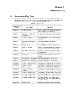
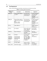
Information related to support and service of Motorola Test Equipment is available via Motorola
Online (Extranet), through the Customer Care Organisation of Motorola’s local area representation
or by calling the Motorola switchboard in Germany on telephone number: +49 6128 700.
Summary of Contents for 6864115B62-C
Page 1: ...Professional Radio GM Series Detailed Service Manual 6864115B62 C ...
Page 2: ...ii ...
Page 4: ...iv ...
Page 5: ...Professional Radio GM Series Service Maintainability Issue July 2007 ...
Page 8: ...ii ...
Page 22: ...2 10 MAINTENANCE ...
Page 25: ...Professional Radio GM Series Controlhead Service Information Issue July 2007 ...
Page 77: ...Professional Radio GM Series Controller Service Information Issue May 2007 ...
Page 100: ...2 2 TROUBLESHOOTING CHARTS ...
Page 104: ...3 4 Controller schematics parts list ...
Page 154: ...3 52 Controller T12 Schematic Diagrams ...
Page 155: ...Professional Radio GM Series VHF 136 174MHz Service Information Issue May 2007 ...
Page 164: ...1 6 MODEL CHART AND TECHNICAL SPECIFICATIONS ...
Page 176: ...2 12 THEORY OF OPERATION ...
Page 186: ...3 10 TROUBLESHOOTING CHARTS ...
Page 190: ...4 4 VHF PCB SCHEMATICS PARTS LISTS ...
Page 252: ...4 66 VHF 1 25W PCB 8471235L02 Schematics VHF 136 174 MHz IF ...
Page 256: ...4 70 VHF 1 25W PCB 8471235L02 Schematics ...
Page 257: ...Professional Radio GM Series UHF 403 470MHz Service Information Issue May 2007 ...
Page 266: ...1 6 MODEL CHART AND TECHNICAL SPECIFICATIONS ...
Page 366: ...2 12 THEORY OF OPERATION ...
Page 372: ...3 6 Low Band TROUBLESHOOTING CHARTS ...


