2-10
THEORY OF OPERATION
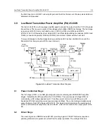
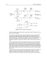
Figure 2-4
LowBand VCO/Buffer Block Diagram
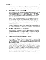
PRE_IN is amplified by feedback buffer Q1202, low-pass filtered by L1205, C1222 and C1224, and
fed to U1201 pin 32 (PREIN).
The pre-scaler in the synthesizer (U1201) is basically a dual modulus pre-scaler with selectable
divider ratios. This divider ratio of the pre-scaler is controlled by the loop divider, which in turn
receives its inputs via the serial interface to the microprocessor. The output of the pre-scaler is
applied to the loop divider. The output of the loop divider is connected to the phase detector, which
compares the loop divider´s output signal with the reference signal. The reference signal is
generated by dividing down the signal of the reference oscillator, whose frequency is controlled by
Y1201.
The output signal of the phase detector is a pulsed DC signal which is routed to the charge pump.
The charge pump outputs a current at pin 43 of U1201 (I OUT). The loop filter (which consists of
R1205-6, R1208, C1212-14) transforms this current into a voltage that is applied to the varactor
diodes (CR1310 for transmit, CR1302 for receive) and alters the output frequency of the appropriate
VCO. The current can be set to a value fixed in the LVFRAC-N IC or to a value determined by the
currents flowing into BIAS 1 (U1201-40) or BIAS 2 (U1201-39). The currents are set by the value of
R1211 or R1207 respectively. The selection of the three different bias sources is done by software
programming.
To reduce synthesizer lock time when new frequency data has been loaded into the synthesizer the
magnitude of the loop current is increased by enabling the IADAPT (U1201-45) for a certain
software programmable time (Adapt Mode). The adapt mode timer is started by a low to high
transient of the CSX line. When the synthesizer is within the lock range the current is determined
STEERING
LINE
(VCTRL)
RXVCO
Q1303
Q1306
TXVCO
AGC
AGC
Q1304
Q1307
Q1308
Q1305
BUFFER
BUFFER
BUFFER
BUFFER
1ST RX
2ND RX
2ND TX
1ST TX
TXINJ
RXINJ
TO Q1202
PRESCALER BUFFER
(TO 1ST MIXER)
(TO U1401 PIN16)
SFOUT
(U1201 PIN28)
U1377-8
DC SWITCH
RX (TO Q1303-5)
TX (TO Q1306-8)
(U1201 PIN2)
~
~
Summary of Contents for 6864115B62-C
Page 1: ...Professional Radio GM Series Detailed Service Manual 6864115B62 C ...
Page 2: ...ii ...
Page 4: ...iv ...
Page 5: ...Professional Radio GM Series Service Maintainability Issue July 2007 ...
Page 8: ...ii ...
Page 22: ...2 10 MAINTENANCE ...
Page 25: ...Professional Radio GM Series Controlhead Service Information Issue July 2007 ...
Page 77: ...Professional Radio GM Series Controller Service Information Issue May 2007 ...
Page 100: ...2 2 TROUBLESHOOTING CHARTS ...
Page 104: ...3 4 Controller schematics parts list ...
Page 154: ...3 52 Controller T12 Schematic Diagrams ...
Page 155: ...Professional Radio GM Series VHF 136 174MHz Service Information Issue May 2007 ...
Page 164: ...1 6 MODEL CHART AND TECHNICAL SPECIFICATIONS ...
Page 176: ...2 12 THEORY OF OPERATION ...
Page 186: ...3 10 TROUBLESHOOTING CHARTS ...
Page 190: ...4 4 VHF PCB SCHEMATICS PARTS LISTS ...
Page 252: ...4 66 VHF 1 25W PCB 8471235L02 Schematics VHF 136 174 MHz IF ...
Page 256: ...4 70 VHF 1 25W PCB 8471235L02 Schematics ...
Page 257: ...Professional Radio GM Series UHF 403 470MHz Service Information Issue May 2007 ...
Page 266: ...1 6 MODEL CHART AND TECHNICAL SPECIFICATIONS ...
Page 366: ...2 12 THEORY OF OPERATION ...
Page 372: ...3 6 Low Band TROUBLESHOOTING CHARTS ...


