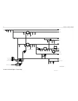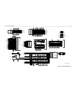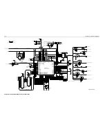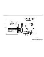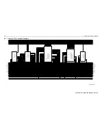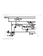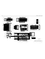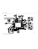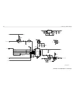
Controller T2 / Schematic Diagrams
3-9
* Motorola Depot Servicing only
Reference designators with an asterisk indicate
components which are not fieldreplaceable
because they need to be calibrated with
specialized factory equipment after installation.
Radios in which these parts have been replaced in
the field will be off frequency at temperature
extremes.
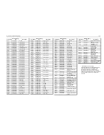
R0101
0662057A73
10K
R0102
0662057A65
4.7K
R0104
0662057A73
10K
R0105
0662057A97
100K
R0108
0662057A57
2.2K
R0111
0662057B47
0
R0113
0662057A73
10K
R0114
0662057A73
10K
R0115
0662057A73
10K
R0117
0662057A63
3.9K
R0121
0662057A97
100K
R0124
0662057B47
0
R0125
0662057A83
27K
R0126
0662057A83
27K
R0127
0662057B47
0
R0128
0662057B47
0
R0131
0662057B46
10MEG
R0132
0662057B10
330K
R0151
0662057A82
24K
R0152
0662057A82
24K
R0170
0662057A73
10K
R0171
0662057A65
4.7K
R0172
0662057A73
10K
R0173
0662057A65
4.7K
R0174
0662057A73
10K
R0175
0662057A73
10K
R0176
0662057A84
30K
R0177
0662057A65
4.7K
R0178
0662057A89
47K
R0179
0662057A89
47K
R0181
0662057A65
4.7K
R0182
0662057A89
47K
R0183
0662057A65
4.7K
R0184
0662057A89
47K
R0185
0662057A65
4.7K
R0186
0662057A89
47K
R0201
0662057A25
100
R0202
0662057A43
560
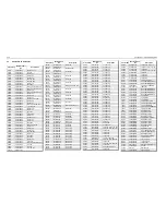
Circuit
Ref
Motorola
Part No.
Description
R0204
0662057A43
560
R0205
0662057A73
10K
R0206
0662057A73
10K
R0207
0662057A57
2.2K
R0208
0662057A57
2.2K
R0211
0660076E70
7.5K
R0212
0660076E70
7.5K
R0221
0662057A82
24K
R0222
0662057A82
24K
R0223
0662057A84
30K
R0224
0662057A71
8.2K
R0226
0662057B22
1MEG
R0227
0662057B22
1MEG
R0241
0662057A89
47K
R0242
0662057B47
0
R0251
0662057A89
47K
R0252
0662057A91
56K
R0253
0662057A97
100K
R0261
0662057A73
10K
R0262
0662057A97
100K
R0265
0662057A82
24K
R0267
0662057A89
47K
R0268
0662057A73
10K
R0269
0662057A41
470
R0273
0662057A82
24K
R0275
0662057A73
10K
R0276
0662057A77
15K
R0401
0662057A33
220
R0407
0662057M26
10
R0408
0662057A25
100
R0409
0662057M26
10
R0467
0662057M26
10
R0468
0662057M26
10
R0481
0662057B47
0
R0482
0662057B47
0
R0510
0662057A65
4.7K
R0511
0662057A97
100K
R0512
0662057A77
15K
Circuit
Ref
Motorola
Part No.
Description
R0523
0662057A33
220
R0524
0662057A33
220
R0525
0662057A97
100K
R0529
0662057A89
47K
R0530
0662057B47
0
R0531
0662057A43
560
R0533
0662057B47
0
R0535
0662057A49
1K
R0537
0662057A33
220
R0538
0662057A33
220
R0539
0662057A65
4.7K
R0541
0662057A83
27K
R0591
0662057A82
24K
R0592
0662057A01
10
R0611
0662057A91
56K
R0612
0662057A65
4.7K
R0621
0662057A82
24K
R0641
0662057A73
10K
R0642
0660076E70
7.5K
R0643
0660076E51
1.2K
R0651
0662057A01
10
R0652
0662057A01
10
R0661
0662057A49
1K
R0662
0662057B02
150K
R0671
0662057A84
30K
R0672
0662057A73
10K
R0681
0662057A79
18K
R0682
0662057A93
68K
U0101
5102226J56
MC68HC11FL0
* U0111
5102463J64
X25128-2.7
* U0121
5186137B01
AT49F040
U0122
5185963A21
63A21
U0125
5105625U34
CDP65C51A
U0141
5113805A30
MC74HC138A
U0211
5183222M49
MC3403
U0221
5185963A53
63A53
U0251
5113806A20
MC14053B
U0271
5109699X01
TDA1519C
Circuit
Ref
Motorola
Part No.
Description
U0611
5183308X01
LM2941
U0641
5183308X01
LM2941
U0651
5113816A07
MC78M05
U0652
5113815A02
MC33064
U0653
4805921T02
NU
VR0151
4813830A15
5.6V
VR0501
4805656W09
20V
VR0503
4805656W09
20V
VR0504
4813830A40
33V
VR0505
4805656W09
20V
VR0509
4813830A40
33V
VR0510
4813830A40
33V
VR0521
4813830A15
5.6V
VR0522
4813830A15
5.6V
VR0537
4813830A15
5.6V
VR0541
4813830A27
14V
VR0601
4813832C77
24V
VR0621
4813830A15
5.6V
Y0131
4880113R19
XTAL
Circuit
Ref
Motorola
Part No.
Description
Summary of Contents for 6864115B62-C
Page 1: ...Professional Radio GM Series Detailed Service Manual 6864115B62 C ...
Page 2: ...ii ...
Page 4: ...iv ...
Page 5: ...Professional Radio GM Series Service Maintainability Issue July 2007 ...
Page 8: ...ii ...
Page 22: ...2 10 MAINTENANCE ...
Page 25: ...Professional Radio GM Series Controlhead Service Information Issue July 2007 ...
Page 77: ...Professional Radio GM Series Controller Service Information Issue May 2007 ...
Page 100: ...2 2 TROUBLESHOOTING CHARTS ...
Page 104: ...3 4 Controller schematics parts list ...
Page 154: ...3 52 Controller T12 Schematic Diagrams ...
Page 155: ...Professional Radio GM Series VHF 136 174MHz Service Information Issue May 2007 ...
Page 164: ...1 6 MODEL CHART AND TECHNICAL SPECIFICATIONS ...
Page 176: ...2 12 THEORY OF OPERATION ...
Page 186: ...3 10 TROUBLESHOOTING CHARTS ...
Page 190: ...4 4 VHF PCB SCHEMATICS PARTS LISTS ...
Page 252: ...4 66 VHF 1 25W PCB 8471235L02 Schematics VHF 136 174 MHz IF ...
Page 256: ...4 70 VHF 1 25W PCB 8471235L02 Schematics ...
Page 257: ...Professional Radio GM Series UHF 403 470MHz Service Information Issue May 2007 ...
Page 266: ...1 6 MODEL CHART AND TECHNICAL SPECIFICATIONS ...
Page 366: ...2 12 THEORY OF OPERATION ...
Page 372: ...3 6 Low Band TROUBLESHOOTING CHARTS ...

