1-4
THEORY OF OPERATION
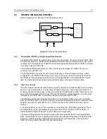
from emitter to collector of the pnp transistor. When the radio is turned on the voltage at the base of
the npn transistor is pulled high and the pnp transistor switches on (saturation). With voltage INT
SWB+ now at supply voltage level, transistor Q0641 pulls pin 2 of the voltage regulators U0611 and
U 0641 to ground level and thereby enables their outputs.
The electronic on/off circuitry can be enabled by the microprocessor (through ASFIC CMP port
GCB2, line DC POWER ON), the emergency switch (line EMERGENCY CONTROL), the
mechanical on/off/volume knob on the controlhead (line ON OFF CONTROL), or the ignition sense
circuitry (line IGNITION CONTROL). If any of the 4 paths cause a low at the collector of the npn
transistor within Q0661, the electronic "ON" is engaged.
1.5
Emergency
The emergency switch (J0501 pin 9), when engaged, grounds the base of Q0662 via line
EMERGENCY CONTROL. This switches Q0662 off and resistor R0662 pulls the collector of Q0662
and the base of Q0663 to levels above 2 volts. Transistor Q0663 switches on and pulls the collector
of the npn transistor within Q0661 to ground level and thereby enables the voltage regulators via
Q0641. When the emergency switch is released R0541 pulls the base of Q0662 up to 0.6 volts. This
causes the collector of transistor Q0662 to go low (0.2V), thereby switching Q0663 off.
While the radio is switched on, the microprocessor monitors the voltage at the emergency input on
the accessory connector via pin 60 and line GP5 IN ACC9. Three different conditions are
distinguished, no emergency, emergency, and open connection to the emergency switch. If no
emergency switch is connected or the connection to the emergency switch is broken, the resistive
divider R0541 / R0512 will set the voltage to about 4.7 volts. If an emergency switch is connected, a
resistor to ground within the emergency switch will reduce the voltage on line GP5 IN ACC9 to
inform the microprocessor that the emergency switch is operational. An engaged emergency switch
pulls line GP5 IN ACC9 to ground level. Diode D0179 limits the voltage to protect the
microprocessor input.
While EMERGENCY CONTROL is low, INT SW B+ is on, the microprocessor starts execution, reads
that the emergency input is active through the voltage level of line GP5 IN ACC9, and sets the DC
POWER ON output of the ASFIC CMP pin 13 to a logic high. This high will keep Q0661 and Q0641
switched on. This operation allows a momentary press of the emergency switch to power up the
radio. When the microprocessor has finished processing the emergency press, it sets the DC
POWER ON line to a logic 0. This turns off Q0661 and the radio turns off. Notice that the
microprocessor is alerted to the emergency condition via line GP5 IN ACC9. If the radio was already
on when emergency was triggered then DC POWER ON would already be high.
1.6
Mechanical ON/OFF
This refers to the typical on/off/volume knob, located on the controlhead, and which turns the radio
on and off.
If the radio is turned off and the on/off/volume knob is pressed, line ON OFF CONTROL (J0401 pin
11) goes high and switches the radio’s voltage regulators on as long as the button is pressed. The
microprocessor is alerted through line ON OFF SENSE (U0101 pin 6) which is pulled to low by
Q0110 while the on/off/volume knob is pressed. In addition, an interrupt is generated at µP pin 96.
The µP asserts line DC POWER ON via ASFIC CMP, pin 13 high which keeps Q0661 and Q0641,
and in turn the radio, switched on. When the on/off/volume knob is released again the controlhead
informs the µP via SBEP bus about the knob release. (See SBEP Serial Interface subsection for
more details). This informs the µP to keep the radio switched on and continue with normal operation.
If the on/off/volume knob is pressed while the radio is on, the controlhead informs the µP via SBEP
bus about the knob status. (See SBEP Serial Interface subsection for more details). After a short
delay time the microprocessor switches the radio off by setting DC POWER ON to low via ASFIC
CMP pin 13.
Summary of Contents for 6864115B62-C
Page 1: ...Professional Radio GM Series Detailed Service Manual 6864115B62 C ...
Page 2: ...ii ...
Page 4: ...iv ...
Page 5: ...Professional Radio GM Series Service Maintainability Issue July 2007 ...
Page 8: ...ii ...
Page 22: ...2 10 MAINTENANCE ...
Page 25: ...Professional Radio GM Series Controlhead Service Information Issue July 2007 ...
Page 77: ...Professional Radio GM Series Controller Service Information Issue May 2007 ...
Page 100: ...2 2 TROUBLESHOOTING CHARTS ...
Page 104: ...3 4 Controller schematics parts list ...
Page 154: ...3 52 Controller T12 Schematic Diagrams ...
Page 155: ...Professional Radio GM Series VHF 136 174MHz Service Information Issue May 2007 ...
Page 164: ...1 6 MODEL CHART AND TECHNICAL SPECIFICATIONS ...
Page 176: ...2 12 THEORY OF OPERATION ...
Page 186: ...3 10 TROUBLESHOOTING CHARTS ...
Page 190: ...4 4 VHF PCB SCHEMATICS PARTS LISTS ...
Page 252: ...4 66 VHF 1 25W PCB 8471235L02 Schematics VHF 136 174 MHz IF ...
Page 256: ...4 70 VHF 1 25W PCB 8471235L02 Schematics ...
Page 257: ...Professional Radio GM Series UHF 403 470MHz Service Information Issue May 2007 ...
Page 266: ...1 6 MODEL CHART AND TECHNICAL SPECIFICATIONS ...
Page 366: ...2 12 THEORY OF OPERATION ...
Page 372: ...3 6 Low Band TROUBLESHOOTING CHARTS ...


