1-4
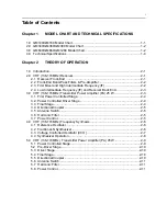
MODEL CHART AND TECHNICAL SPECIFICATIONS
4.0
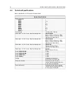
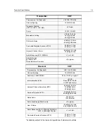
Technical Specifications
Data is specified for +25°C unless otherwise stated.
General Specifications
Channel Capacity
GM140
GM160
GM340
GM360
GM380
GM640
GM660
GM1280
Databox
4
128
6
255
255
6
255
255
16
Power Supply
13.2Vdc (10.8 - 15.6Vdc)
Dimensions: H x W x D (mm) Depth excluding knobs
GM140/340/640
56mm x 176mm x 177mm (1 - 25W)
56mm x 176mm x 189mm (25 - 45W)
(add 8mm for Volume Knob)
Dimensions: H x W x D (mm) Depth excluding knobs
GM160/360/660
59mm x 179mm x 186mm (1 - 25W)
59mm x 179mm x 198mm (25 - 45W)
(add 9mm for Volume Knob)
Dimensions: H x W x D (mm) Depth excluding knobs
GM380/1280
188mm x 185mm x 72mm
(add 8mm for Volume Knob)
Dimensions: H x W x D (mm) Depth excluding knobs
Databox
44mm x 168mm x 161mm
Weight
GM140/340/640
1400gr
Weight
GM160/360/660
1400gr
Weight
GM380/1280
1500gr
Weight
Databox
1220gr
Sealing:
Withstands rain testing per
MIL STD 810 C/D /E and IP54
Shock and Vibration:
Protection provided via impact
resistant housing exceeding MIL STD
810-C/D /E and TIA/EIA 603
Dust and Humidity:
Protection provided via environment
resistant housing exceeding MIL STD
810 C/D /E and TIA/EIA 603
Summary of Contents for 6864115B62-C
Page 1: ...Professional Radio GM Series Detailed Service Manual 6864115B62 C ...
Page 2: ...ii ...
Page 4: ...iv ...
Page 5: ...Professional Radio GM Series Service Maintainability Issue July 2007 ...
Page 8: ...ii ...
Page 22: ...2 10 MAINTENANCE ...
Page 25: ...Professional Radio GM Series Controlhead Service Information Issue July 2007 ...
Page 77: ...Professional Radio GM Series Controller Service Information Issue May 2007 ...
Page 100: ...2 2 TROUBLESHOOTING CHARTS ...
Page 104: ...3 4 Controller schematics parts list ...
Page 154: ...3 52 Controller T12 Schematic Diagrams ...
Page 155: ...Professional Radio GM Series VHF 136 174MHz Service Information Issue May 2007 ...
Page 164: ...1 6 MODEL CHART AND TECHNICAL SPECIFICATIONS ...
Page 176: ...2 12 THEORY OF OPERATION ...
Page 186: ...3 10 TROUBLESHOOTING CHARTS ...
Page 190: ...4 4 VHF PCB SCHEMATICS PARTS LISTS ...
Page 252: ...4 66 VHF 1 25W PCB 8471235L02 Schematics VHF 136 174 MHz IF ...
Page 256: ...4 70 VHF 1 25W PCB 8471235L02 Schematics ...
Page 257: ...Professional Radio GM Series UHF 403 470MHz Service Information Issue May 2007 ...
Page 266: ...1 6 MODEL CHART AND TECHNICAL SPECIFICATIONS ...
Page 366: ...2 12 THEORY OF OPERATION ...
Page 372: ...3 6 Low Band TROUBLESHOOTING CHARTS ...


