2-8
THEORY OF OPERATION
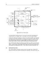
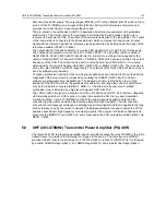
Figure 2-4
UHF VCO Block Diagram
a low enables RX tank and RX output (pin 8). A sample of the signal from the enabled output is
routed from U4301 pin 12 (PRESC_OUT), via a low pass filter, to pin 32 of U4201 (PREIN).
A steering line voltage (VCTRL) between 3.0V and 10.0V at varactor diode CR4311 will tune the full
TX frequency range (TXINJ) from 403 MHz to 470 MHz, and at varactor diodes CR4301, CR4302
and CR4303 will tune the full RX frequency range (RXINJ) from 358 MHz to 425 MHz. The tank
circuits uses the Hartley configuration for wider bandwidth. For the RX tank circuit, an external
transistor Q4301 is used in conjunction with the internal transistor for better side-band noise.
The external RX buffers (Q4332) are enabled by a high at U4201 pin 3 (AUX4) via transistor switch
Q4333. In TX mode the modulation signal (VCOMOD) from the LVFRAC-N synthesizer IC (U4201
pin41) is applied modulation circuitry CR4321, R4321, R4322 and C4324, which modulates the TX
VCO frequency via coupling capacitor C4321. Varactor CR4321 is biased for linearity from VSF.
4.4
Synthesizer Operation
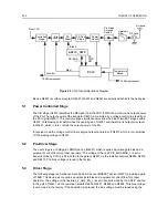
The complete synthesizer subsystem comprises mainly of low voltage FRAC-N (LVFRACN) IC,
Reference Oscillator (crystal oscillator with temperature compensation), charge pump circuitry, loop
Presc
RX
TX
Matching
Network
Low Pass
Filter
Attenuator
Pin8
Pin14
Pin10
(U4201 Pin28)
VCC Buffers
TX RF Injection
U4201 Pin 32
AUX3 (U4201 Pin 2)
Prescaler Out
Pin 12
Pin 19
Pin 20
TX/RX/BS
Switching Network
U4301
VCOBIC
Rx
Active Bias
Tx
Active Bias
Pin2
Rx-I adjust
Pin1
Tx-I adjust
Pins 9,11,17
Pin18
Vsens
Circuit
Pin15
Pin16
RX VCO
Circuit
TX VCO
Circuit
RX Tank
TX Tank
Pin7
Vcc-Superfilter
Collector/RF in
Pin4
Pin5
Pin6
RX
TX
(U4201 Pin 28)
Rx-SW
Tx-SW
Vcc-Logic
(U4201 Pin 28)
Steer Line
Voltage
(VCTRL)
Pin13
Pin3
TRB IN
LO RF INJECTION
Q4301
Q4332
Summary of Contents for 6864115B62-C
Page 1: ...Professional Radio GM Series Detailed Service Manual 6864115B62 C ...
Page 2: ...ii ...
Page 4: ...iv ...
Page 5: ...Professional Radio GM Series Service Maintainability Issue July 2007 ...
Page 8: ...ii ...
Page 22: ...2 10 MAINTENANCE ...
Page 25: ...Professional Radio GM Series Controlhead Service Information Issue July 2007 ...
Page 77: ...Professional Radio GM Series Controller Service Information Issue May 2007 ...
Page 100: ...2 2 TROUBLESHOOTING CHARTS ...
Page 104: ...3 4 Controller schematics parts list ...
Page 154: ...3 52 Controller T12 Schematic Diagrams ...
Page 155: ...Professional Radio GM Series VHF 136 174MHz Service Information Issue May 2007 ...
Page 164: ...1 6 MODEL CHART AND TECHNICAL SPECIFICATIONS ...
Page 176: ...2 12 THEORY OF OPERATION ...
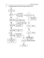
Page 186: ...3 10 TROUBLESHOOTING CHARTS ...
Page 190: ...4 4 VHF PCB SCHEMATICS PARTS LISTS ...
Page 252: ...4 66 VHF 1 25W PCB 8471235L02 Schematics VHF 136 174 MHz IF ...
Page 256: ...4 70 VHF 1 25W PCB 8471235L02 Schematics ...
Page 257: ...Professional Radio GM Series UHF 403 470MHz Service Information Issue May 2007 ...
Page 266: ...1 6 MODEL CHART AND TECHNICAL SPECIFICATIONS ...
Page 366: ...2 12 THEORY OF OPERATION ...
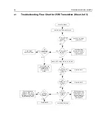
Page 372: ...3 6 Low Band TROUBLESHOOTING CHARTS ...


