3-2
SERVICE AIDS
2.0
Test Equipment
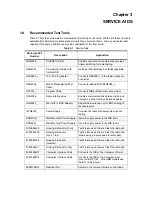
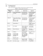
Table 3-2 lists test equipment required to service the radio and other two-way radios.
Table 3-2
Recommended Test Equipment
Motorola Part
Number
Description
Characteristics
Application
R2600_NT
Comms System Analyzer
(non MPT)
This monitor will
substitute for items
with an asterisk*
Frequency/deviation
meter and signal
generator for
widerange
troubleshooting and
alignment
R2680_NT
Comms System Analyzer
( MPT1327) to be ordered
with
RLN1022_ (H/W)
RLN1023_ (S/W)
This monitor will
substitute for items
with an asterisk*.
Frequency/deviation
meter and signal
generator for
widerange
troubleshooting and
alignment
*R1072_
Digital Multimeter
AC/DC voltage and
current
measurements
*R-1377_
AC Voltmeter
100µV to 300V, 5Hz -
1MHz, 10Megohm
input impedance
Audio voltage
measurements
WADN133_
Delay Oscilloscope
2 Channel 40MHz
bandwidth,
5mV/cm - 20 V/cm
Waveform
measurements
R1440_
0180305F17
0180305F31
0180305F39
RLN4610_
T1013_
Wattmeter,
Plug-in Elements
Plug-in Elements
Plug-in Elements
Carry case
RF Dummy Load
Thruline 50-Ohm,
±5% accuracy
100W, 25 - 60MHz
25W, 100-250MHz
10W, 200-250MHz
Wattmeter and
6 elements
Transmitter power
output
measurements
S1339_
RF Millivolt Meter
100mV to 3 VRF.
10kHz to 1.2GHz
RF level
measurements
R1011_/220V
220V Power Supply
0 - 40V 0 - 40A
Programmable
Summary of Contents for 6864115B62-C
Page 1: ...Professional Radio GM Series Detailed Service Manual 6864115B62 C ...
Page 2: ...ii ...
Page 4: ...iv ...
Page 5: ...Professional Radio GM Series Service Maintainability Issue July 2007 ...
Page 8: ...ii ...
Page 22: ...2 10 MAINTENANCE ...
Page 25: ...Professional Radio GM Series Controlhead Service Information Issue July 2007 ...
Page 77: ...Professional Radio GM Series Controller Service Information Issue May 2007 ...
Page 100: ...2 2 TROUBLESHOOTING CHARTS ...
Page 104: ...3 4 Controller schematics parts list ...
Page 154: ...3 52 Controller T12 Schematic Diagrams ...
Page 155: ...Professional Radio GM Series VHF 136 174MHz Service Information Issue May 2007 ...
Page 164: ...1 6 MODEL CHART AND TECHNICAL SPECIFICATIONS ...
Page 176: ...2 12 THEORY OF OPERATION ...
Page 186: ...3 10 TROUBLESHOOTING CHARTS ...
Page 190: ...4 4 VHF PCB SCHEMATICS PARTS LISTS ...
Page 252: ...4 66 VHF 1 25W PCB 8471235L02 Schematics VHF 136 174 MHz IF ...
Page 256: ...4 70 VHF 1 25W PCB 8471235L02 Schematics ...
Page 257: ...Professional Radio GM Series UHF 403 470MHz Service Information Issue May 2007 ...
Page 266: ...1 6 MODEL CHART AND TECHNICAL SPECIFICATIONS ...
Page 366: ...2 12 THEORY OF OPERATION ...
Page 372: ...3 6 Low Band TROUBLESHOOTING CHARTS ...

