


i
Table of Contents
Chapter 1
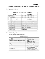
MODEL CHART AND TECHNICAL SPECIFICATIONS
1.0 GM360 Model Chart.............................................................................................1-1
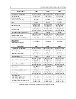
2.0 Technical Specifications ......................................................................................1-1
Chapter 2
THEORY OF OPERATION
1.0 Introduction ..........................................................................................................2-1
2.0 Low Band Receiver..............................................................................................2-2
2.1 Receiver Front-End .......................................................................................2-2
2.2 Front-End Band-Pass Filters & Pre-Amplifier .................................................2-3
2.3 First Mixer and High Intermediate Frequency (IF) .........................................2-3
2.4 High Intermediate Frequency (IF) and Blanker Switches ...............................2-3
2.5 Low Intermediate Frequency (IF) and Receiver Back End.............................2-4
2.6 "Extender" (Noise Blanker).............................................................................2-4
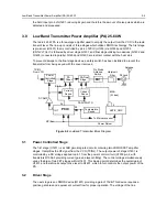
3.0 Low Band Transmitter Power Amplifier (PA) 25-60 W .........................................2-5
3.1 Power Controlled Stage..................................................................................2-5
3.2 Driver Stage....................................................................................................2-5
3.3 Final Stage......................................................................................................2-6
3.4 Antenna Switch...............................................................................................2-6
3.5 Harmonic Filter ...............................................................................................2-6
3.6 Power Control.................................................................................................2-7
3.7 TX Safety Switch ............................................................................................2-7
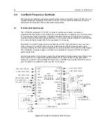
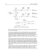
4.0 Low Band Frequency Synthesis ..........................................................................2-8
4.1 Fractional-N Synthesizer ................................................................................2-8
4.2 Voltage Controlled Oscillator (VCO) ...............................................................2-9
4.3 Synthesizer Operation ....................................................................................2-9
Chapter 3
TROUBLESHOOTING CHARTS
1.0 Troubleshooting Flow Chart for Transmitter .......................................................3-1
2.0 Troubleshooting Flow Chart for Receiver (Sheet 1 of 2)......................................3-2
2.1 Troubleshooting Flow Chart for Receiver (Sheet 2 of 2)......................................3-3
3.0 Troubleshooting Flow Chart for Synthesizer........................................................3-4
4.0 Troubleshooting Flow Chart for VCO .................................................................3-5
Summary of Contents for 6864115B62-C
Page 1: ...Professional Radio GM Series Detailed Service Manual 6864115B62 C ...
Page 2: ...ii ...
Page 4: ...iv ...
Page 5: ...Professional Radio GM Series Service Maintainability Issue July 2007 ...
Page 8: ...ii ...
Page 22: ...2 10 MAINTENANCE ...
Page 25: ...Professional Radio GM Series Controlhead Service Information Issue July 2007 ...
Page 77: ...Professional Radio GM Series Controller Service Information Issue May 2007 ...
Page 100: ...2 2 TROUBLESHOOTING CHARTS ...
Page 104: ...3 4 Controller schematics parts list ...
Page 154: ...3 52 Controller T12 Schematic Diagrams ...
Page 155: ...Professional Radio GM Series VHF 136 174MHz Service Information Issue May 2007 ...
Page 164: ...1 6 MODEL CHART AND TECHNICAL SPECIFICATIONS ...
Page 176: ...2 12 THEORY OF OPERATION ...
Page 186: ...3 10 TROUBLESHOOTING CHARTS ...
Page 190: ...4 4 VHF PCB SCHEMATICS PARTS LISTS ...
Page 252: ...4 66 VHF 1 25W PCB 8471235L02 Schematics VHF 136 174 MHz IF ...
Page 256: ...4 70 VHF 1 25W PCB 8471235L02 Schematics ...
Page 257: ...Professional Radio GM Series UHF 403 470MHz Service Information Issue May 2007 ...
Page 266: ...1 6 MODEL CHART AND TECHNICAL SPECIFICATIONS ...
Page 366: ...2 12 THEORY OF OPERATION ...
Page 372: ...3 6 Low Band TROUBLESHOOTING CHARTS ...