


Troubleshooting Flow Chart for 25W Transmitter (Sheet 1 of 3)
3-5
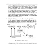
2.2
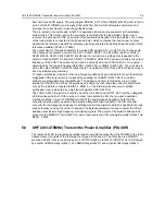
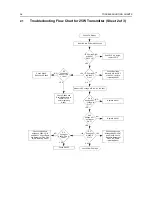
Troubleshooting Flow Chart for 25W Transmitter (Sheet 3 of 3
)
Check Final PA Stage
NO
0V
1-4V
Bias 2 DC
Voltage at
TP4406?
YES
RF Voltage
at TP4401
>100mV?
YES
RF Voltage
U4401 Pin 6
>3V?
Supply
Replace Q4441
Check FGU (U4301)
NO
Check Components
between
TP4401 &C4417
NO
YES
ASFIC
U0221 Pin 6
1-4V DC?
Check Bias Tuning
before replacing ASFIC
U0221
Check Components
between ASFIC and
Q4441 before
replacing Q4441
YES
RF Voltage
Q4421 Gate
>1V?
NO
Check Components
between
C4417 & Q4421
YES
RF Voltage
Q4441 Gate
>4V?
NO
Check Components
between
Q4421 & Q4441
Check Components
between Q4441 &
Antenna Connector
Voltage
Summary of Contents for 6864115B62-C
Page 1: ...Professional Radio GM Series Detailed Service Manual 6864115B62 C ...
Page 2: ...ii ...
Page 4: ...iv ...
Page 5: ...Professional Radio GM Series Service Maintainability Issue July 2007 ...
Page 8: ...ii ...
Page 22: ...2 10 MAINTENANCE ...
Page 25: ...Professional Radio GM Series Controlhead Service Information Issue July 2007 ...
Page 77: ...Professional Radio GM Series Controller Service Information Issue May 2007 ...
Page 100: ...2 2 TROUBLESHOOTING CHARTS ...
Page 104: ...3 4 Controller schematics parts list ...
Page 154: ...3 52 Controller T12 Schematic Diagrams ...
Page 155: ...Professional Radio GM Series VHF 136 174MHz Service Information Issue May 2007 ...
Page 164: ...1 6 MODEL CHART AND TECHNICAL SPECIFICATIONS ...
Page 176: ...2 12 THEORY OF OPERATION ...
Page 186: ...3 10 TROUBLESHOOTING CHARTS ...
Page 190: ...4 4 VHF PCB SCHEMATICS PARTS LISTS ...
Page 252: ...4 66 VHF 1 25W PCB 8471235L02 Schematics VHF 136 174 MHz IF ...
Page 256: ...4 70 VHF 1 25W PCB 8471235L02 Schematics ...
Page 257: ...Professional Radio GM Series UHF 403 470MHz Service Information Issue May 2007 ...
Page 266: ...1 6 MODEL CHART AND TECHNICAL SPECIFICATIONS ...
Page 366: ...2 12 THEORY OF OPERATION ...
Page 372: ...3 6 Low Band TROUBLESHOOTING CHARTS ...