


Controller Board Audio and Signalling Circuits
1-17
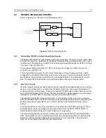
2.5
RECEIVE SIGNALLING CIRCUITS
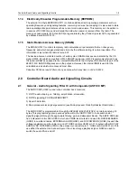
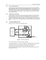
Refer to Figure 5-6 for reference for the following sections.
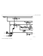
Figure 6-1
Receive Signalling Paths
2.5.1
Sub-audible (PL/DPL) and High Speed Data Decoder
The ASFIC CMP (U0221) is used to filter and limit all received data. The data enters the ASFIC CMP
at input DISC (U0221-2). Inside U0221 the data is filtered according to data type (HS or LS), then it
is limited to a 0-5V digital level. The MDC and trunking high speed data appear at U0221-19, where
it connects to the µP U0101-82.
The low speed limited data output (PL, DPL, and trunking LS) appears at U0221-18, where it
connects to the µP U0101-80.
The low speed data is read by the µP at twice the frequency of the sampling waveform; a latch
configuration in the ASFIC CMP stores one bit every clock cycle. The external capacitors C0236,
and C0244 set the low frequency pole for a zero crossings detector in the limiters for PL and HS
data. The hysterisis of these limiters is programmed based on the type of received data.
2.5.2
Alert Tone Circuits
When the software determines that it needs to give the operator an audible feedback (for a good key
press, or for a bad key press), or radio status (trunked system busy, phone call, circuit failures), it
sends an alert tone to the speaker. It does so by sending SPI BUS data to U0221 which sets up the
audio path to the speaker for alert tones. The alert tone itself can be generated in one of two ways:
internally by the ASFIC CMP, or externally using the µP and the ASFIC CMP.
The allowable internal alert tones are 304, 608, 911, and 1823Hz. In this case a code contained
within the SPI BUS load to the ASFIC CMP sets up the path and determines the tone frequency, and
at what volume level to generate the tone. (It does not have to be related to the voice volume
setting).
For external alert tones, the µP can generate any tone within the 100-3000Hz audio band. This is
accomplished by the µP generating a square wave which enters the ASFIC CMP at U0221-19.
Inside the ASFIC CMP this signal is routed to the alert tone generator.
The output of the generator is summed into the audio chain just after the RX audio de-emphasis
block. Inside U0221 the tone is amplified and filtered, then passed through the 8-bit digital volume
attenuator, which is typically loaded with a special value for alert tone audio. The tone exits at
U0221-41 and is routed to the audio PA like receive audio.
DET AUDIO
DISCRIMINATOR AUDIO
FROM RF SECTION
(IF IC)
19
18
25
2
82
80
DISC
PLCAP2
LSIO
HSIO
DATA FILTER
AND DEEMPHASIS
LIMITER
FILTER
LIMITER
ASFIC_CMP
U0221
MICRO
CONTROLLER
U0101
85
44
8
PLCAP
Summary of Contents for 6864115B62-C
Page 1: ...Professional Radio GM Series Detailed Service Manual 6864115B62 C ...
Page 2: ...ii ...
Page 4: ...iv ...
Page 5: ...Professional Radio GM Series Service Maintainability Issue July 2007 ...
Page 8: ...ii ...
Page 22: ...2 10 MAINTENANCE ...
Page 25: ...Professional Radio GM Series Controlhead Service Information Issue July 2007 ...
Page 77: ...Professional Radio GM Series Controller Service Information Issue May 2007 ...
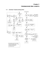
Page 100: ...2 2 TROUBLESHOOTING CHARTS ...
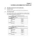
Page 104: ...3 4 Controller schematics parts list ...
Page 154: ...3 52 Controller T12 Schematic Diagrams ...
Page 155: ...Professional Radio GM Series VHF 136 174MHz Service Information Issue May 2007 ...
Page 164: ...1 6 MODEL CHART AND TECHNICAL SPECIFICATIONS ...
Page 176: ...2 12 THEORY OF OPERATION ...
Page 186: ...3 10 TROUBLESHOOTING CHARTS ...
Page 190: ...4 4 VHF PCB SCHEMATICS PARTS LISTS ...
Page 252: ...4 66 VHF 1 25W PCB 8471235L02 Schematics VHF 136 174 MHz IF ...
Page 256: ...4 70 VHF 1 25W PCB 8471235L02 Schematics ...
Page 257: ...Professional Radio GM Series UHF 403 470MHz Service Information Issue May 2007 ...
Page 266: ...1 6 MODEL CHART AND TECHNICAL SPECIFICATIONS ...
Page 366: ...2 12 THEORY OF OPERATION ...
Page 372: ...3 6 Low Band TROUBLESHOOTING CHARTS ...