


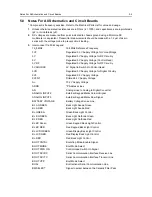


Notes For All Schematics and Circuit Boards
2-7
IN 5V RF REG
Supply Voltage for 5V Regulator in RF Section
INT KP COL
Internal Keypad Matrix Column Signal
INT KP ROW
Internal Keypad Matrix Row Signal
INT MIC
Internal (from Control Head) Microphone Input
INT SWB
Internal Switched 13.2V Supply Voltage
INT SWB+
Internal Switched 13.2V Supply Voltage
IRQ
Interrupt Request from Control Head
K9V1
9.1V in Transmit Mode
KEYPAD ID
Keypad Identification Line
LCD A0
LCD Control / Display Data Select
LCD CS
LCD Chip Select
LCD DATA
LCD Data Lines
LCD E RD
LCD Enable Read
LCD RW WR
LCD Read Write Control
LED CNTRL
LED Control Lines
LED GREEN
Green LED Control
LED RED
Red LED Control
LED YELLOW
Yellow LED Control
LOCK
Lock Detect Signal from Synthesizer
LSIO
Low Speed Clock In / Data Out
LVZIF CS
LVZIF Chip Select (not used)
MIC
Microphone Input
MISO
Serial Peripheral Interface Receive Line
MODIN
Modulation Signal into the Synthesizer
MOSBIAS 2
PA Bias Voltage for second Stage
MOSBIAS 3
PA Bias Voltage for third Stage
NOISE BLNKR
Noise Blanker Enable (Low Band only)
ON OFF CONTROL
Service Request Line from Control Head / Manual Switching On
of the Radio's Voltage Regulators
ON OFF SENSE (Control Head) On Off Sense Line to Control Head *P
ON OFF SENSE (Controller)
Service Request Line from Control Head
OPT CS
Option Board Chip Select
OPT PTT
PTT from Option Board
PA PWR SET
ASFIC Output Voltage to set the Transmitter Power
PA SWB
Switches Supply Voltage for PA Current Control Circuitry
PASUPVLTG
13.2 V Supply Voltage of the Transmitter PA
PCIC MOSBIAS 1
PA Bias Voltage for first Stage
PRESC
Prescaler Signal from VCO to Synthesizer
PTT IRDEC
Microphone PTT Input
PTT IRDECODER
Microphone PTT Input
R W
Read Write Signal for RAM / Flash
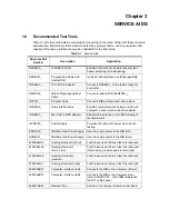
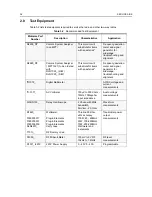
Summary of Contents for 6864115B62-C
Page 1: ...Professional Radio GM Series Detailed Service Manual 6864115B62 C ...
Page 2: ...ii ...
Page 4: ...iv ...
Page 5: ...Professional Radio GM Series Service Maintainability Issue July 2007 ...
Page 8: ...ii ...
Page 22: ...2 10 MAINTENANCE ...
Page 25: ...Professional Radio GM Series Controlhead Service Information Issue July 2007 ...
Page 77: ...Professional Radio GM Series Controller Service Information Issue May 2007 ...
Page 100: ...2 2 TROUBLESHOOTING CHARTS ...
Page 104: ...3 4 Controller schematics parts list ...
Page 154: ...3 52 Controller T12 Schematic Diagrams ...
Page 155: ...Professional Radio GM Series VHF 136 174MHz Service Information Issue May 2007 ...
Page 164: ...1 6 MODEL CHART AND TECHNICAL SPECIFICATIONS ...
Page 176: ...2 12 THEORY OF OPERATION ...
Page 186: ...3 10 TROUBLESHOOTING CHARTS ...
Page 190: ...4 4 VHF PCB SCHEMATICS PARTS LISTS ...
Page 252: ...4 66 VHF 1 25W PCB 8471235L02 Schematics VHF 136 174 MHz IF ...
Page 256: ...4 70 VHF 1 25W PCB 8471235L02 Schematics ...
Page 257: ...Professional Radio GM Series UHF 403 470MHz Service Information Issue May 2007 ...
Page 266: ...1 6 MODEL CHART AND TECHNICAL SPECIFICATIONS ...
Page 366: ...2 12 THEORY OF OPERATION ...
Page 372: ...3 6 Low Band TROUBLESHOOTING CHARTS ...