Chapter 4
VHF PCB/SCHEMATICS/PARTS LISTS
1.0
Allocation of Schematics and Circuit Boards
1.1
Controller Circuits
The VHF circuits are contained on the printed circuit board (PCB) which also contains the Controller
circuits. This Chapter shows the schematics for the VHF circuits only, refer to the Controller section
for details of the related Controller circuits . The PCB component layouts and the Parts Lists in this
Chapter show both the Controller and VHF circuit components. The VHF schematics and the related
PCB and parts list are shown in the tables below.
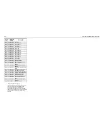
Table 4-1
VHF 1-25W Diagrams and Parts Lists
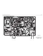
PCB :
8486172B04
Main Board Top Side
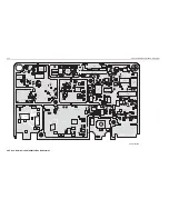
8486172B04
Main Board Bottom Side
Page 4-5
Page 4-6
SCHEMATICS
Power Amplifier 1 - 25W
FRACN
Voltage Controlled Oscillator
Receiver Front End
IF
Page 4-7
Page 4-8
Page 4-9
Page 4-10
Page 4-11
Parts List
8486172B04
Page 4-12
Controller
version is
T2
Table 4-2
VHF 1-25W Diagrams and Parts Lists
PCB :
8486172B06
Main Board Top Side
8486172B06
Main Board Bottom Side
Page 4-15
Page 4-16
SCHEMATICS
Power Amplifier 1 - 25W
FRACN
Voltage Controlled Oscillator
Receiver Front End
IF
Page 4-17
Page 4-18
Page 4-19
Page 4-20
Page 4-21
Parts List
8486172B06
Page 4-22
Controller
version is
T5
Table 4-3
VHF 1-25W Diagrams and Parts Lists
PCB :
8486172B07
Main Board Top Side
8486172B07
Main Board Bottom Side
Page 4-25
Page 4-26
SCHEMATICS
IF
FRACN
Page 4-27
Page 4-28
Parts List: 8486172B07
Page 4-29
Controller
version is
T7
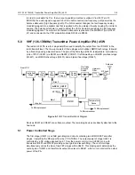
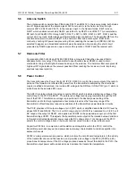
Summary of Contents for 6864115B62-C
Page 1: ...Professional Radio GM Series Detailed Service Manual 6864115B62 C ...
Page 2: ...ii ...
Page 4: ...iv ...
Page 5: ...Professional Radio GM Series Service Maintainability Issue July 2007 ...
Page 8: ...ii ...
Page 22: ...2 10 MAINTENANCE ...
Page 25: ...Professional Radio GM Series Controlhead Service Information Issue July 2007 ...
Page 77: ...Professional Radio GM Series Controller Service Information Issue May 2007 ...
Page 100: ...2 2 TROUBLESHOOTING CHARTS ...
Page 104: ...3 4 Controller schematics parts list ...
Page 154: ...3 52 Controller T12 Schematic Diagrams ...
Page 155: ...Professional Radio GM Series VHF 136 174MHz Service Information Issue May 2007 ...
Page 164: ...1 6 MODEL CHART AND TECHNICAL SPECIFICATIONS ...
Page 176: ...2 12 THEORY OF OPERATION ...
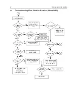
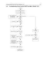
Page 186: ...3 10 TROUBLESHOOTING CHARTS ...
Page 190: ...4 4 VHF PCB SCHEMATICS PARTS LISTS ...
Page 252: ...4 66 VHF 1 25W PCB 8471235L02 Schematics VHF 136 174 MHz IF ...
Page 256: ...4 70 VHF 1 25W PCB 8471235L02 Schematics ...
Page 257: ...Professional Radio GM Series UHF 403 470MHz Service Information Issue May 2007 ...
Page 266: ...1 6 MODEL CHART AND TECHNICAL SPECIFICATIONS ...
Page 366: ...2 12 THEORY OF OPERATION ...
Page 372: ...3 6 Low Band TROUBLESHOOTING CHARTS ...

