


3-2
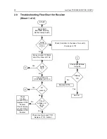
Low Band TROUBLESHOOTING CHARTS
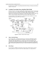
2.0
Troubleshooting Flow Chart for Receiver
(Sheet 1 of 2)
Check
circuitry
around U1103.
Replace U1103
if defect.
Check circuitry
around U1103.
Replace U1103
if defect.
Audio
at pin 8 of
U1103
?
Audio
heard
?
Check
voltages on
U1103.
OK?
Bad SINAD
Bad 20dB Quieting
No Recovered Audio
START
Check Controller (in the case of no audio).
Or else go to “B”
Yes
No
Spray or inject 10.7MHz
into XTAL Filter FL1102.
B
Yes
No
Check 2nd LO
(10.245MHz) at C1129.
LO
present
B
Yes
Biasing
OK
No
No
A
Yes
Check Q1106 bias
for faults.
Replace Q1106.
Go to B
Yes
No
Check circuitry around Y1101.
Replace Y1101 if defect.
Summary of Contents for 6864115B62-C
Page 1: ...Professional Radio GM Series Detailed Service Manual 6864115B62 C ...
Page 2: ...ii ...
Page 4: ...iv ...
Page 5: ...Professional Radio GM Series Service Maintainability Issue July 2007 ...
Page 8: ...ii ...
Page 22: ...2 10 MAINTENANCE ...
Page 25: ...Professional Radio GM Series Controlhead Service Information Issue July 2007 ...
Page 77: ...Professional Radio GM Series Controller Service Information Issue May 2007 ...
Page 100: ...2 2 TROUBLESHOOTING CHARTS ...
Page 104: ...3 4 Controller schematics parts list ...
Page 154: ...3 52 Controller T12 Schematic Diagrams ...
Page 155: ...Professional Radio GM Series VHF 136 174MHz Service Information Issue May 2007 ...
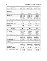
Page 164: ...1 6 MODEL CHART AND TECHNICAL SPECIFICATIONS ...
Page 176: ...2 12 THEORY OF OPERATION ...
Page 186: ...3 10 TROUBLESHOOTING CHARTS ...
Page 190: ...4 4 VHF PCB SCHEMATICS PARTS LISTS ...
Page 252: ...4 66 VHF 1 25W PCB 8471235L02 Schematics VHF 136 174 MHz IF ...
Page 256: ...4 70 VHF 1 25W PCB 8471235L02 Schematics ...
Page 257: ...Professional Radio GM Series UHF 403 470MHz Service Information Issue May 2007 ...
Page 266: ...1 6 MODEL CHART AND TECHNICAL SPECIFICATIONS ...
Page 366: ...2 12 THEORY OF OPERATION ...
Page 372: ...3 6 Low Band TROUBLESHOOTING CHARTS ...