


ii
Chapter 3
TROUBLESHOOTING CHARTS
1.0 Troubleshooting Flow Chart for Receiver (Sheet 1 of 2) ..................................... 3-1
1.1 Troubleshooting Flow Chart for Receiver (Sheet 2 of 2) ..................................... 3-2
2.0 Troubleshooting Flow Chart for 25W Transmitter (Sheet 1 of 3) ......................... 3-3
2.1 Troubleshooting Flow Chart for 25W Transmitter (Sheet 2 of 3) ......................... 3-4
2.2 Troubleshooting Flow Chart for 25W Transmitter (Sheet 3 of 3) ......................... 3-5
3.0 Troubleshooting Flow Chart for 40W Transmitter ............................................... 3-6
4.0 Troubleshooting Flow Chart for Synthesizer........................................................ 3-7
5.0 Troubleshooting Flow Chart for VCO................................................................... 3-8
Chapter 4
UHF PCB/SCHEMATICS/PARTS LISTS
1.0 Allocation of Schematics and Circuit Boards ....................................................... 4-1
1.1 Controller Circuits ................................................................................................ 4-1
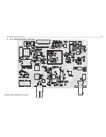
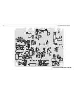
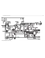
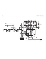
2.0 UHF 1-25W PCB 8485670Z02 / Schematics....................................................... 4-3
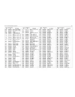
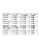
2.1 UHF 1-25W PCB 8485670Z02 Parts List .......................................................... 4-10
3.0 UHF 25-40W PCB 8480643Z06 / Schematics................................................... 4-13
3.1 UHF 25-40W PCB 8480643Z06 Parts List ........................................................ 4-20
4.0 UHF 1-25W PCB 8485670Z03 / Schematics..................................................... 4-23
4.1 UHF 1-25W PCB 8485670Z03 Parts List .......................................................... 4-30
5.0 UHF 1-25W PCB 8486127Z01 / Schematics..................................................... 4-33
5.1 UHF 1-25W PCB 8486127Z01 Parts List .......................................................... 4-40
6.0 UHF 1-25W PCB 8471224L01 / Schematics ..................................................... 4-43
6.1 UHF 1-25W PCB 8471224L01 Parts List .......................................................... 4-46
7.0 UHF 1-25W PCB 8471224L03 .......................................................................... 4-49
7.1 UHF 1-25W PCB 8471224L03 Parts List .......................................................... 4-57
Summary of Contents for 6864115B62-C
Page 1: ...Professional Radio GM Series Detailed Service Manual 6864115B62 C ...
Page 2: ...ii ...
Page 4: ...iv ...
Page 5: ...Professional Radio GM Series Service Maintainability Issue July 2007 ...
Page 8: ...ii ...
Page 22: ...2 10 MAINTENANCE ...
Page 25: ...Professional Radio GM Series Controlhead Service Information Issue July 2007 ...
Page 77: ...Professional Radio GM Series Controller Service Information Issue May 2007 ...
Page 100: ...2 2 TROUBLESHOOTING CHARTS ...
Page 104: ...3 4 Controller schematics parts list ...
Page 154: ...3 52 Controller T12 Schematic Diagrams ...
Page 155: ...Professional Radio GM Series VHF 136 174MHz Service Information Issue May 2007 ...
Page 164: ...1 6 MODEL CHART AND TECHNICAL SPECIFICATIONS ...
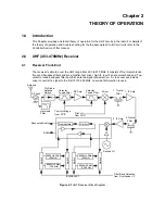
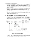
Page 176: ...2 12 THEORY OF OPERATION ...
Page 186: ...3 10 TROUBLESHOOTING CHARTS ...
Page 190: ...4 4 VHF PCB SCHEMATICS PARTS LISTS ...
Page 252: ...4 66 VHF 1 25W PCB 8471235L02 Schematics VHF 136 174 MHz IF ...
Page 256: ...4 70 VHF 1 25W PCB 8471235L02 Schematics ...
Page 257: ...Professional Radio GM Series UHF 403 470MHz Service Information Issue May 2007 ...
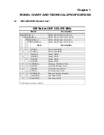
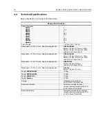
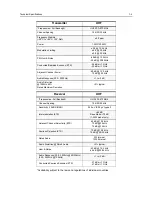
Page 266: ...1 6 MODEL CHART AND TECHNICAL SPECIFICATIONS ...
Page 366: ...2 12 THEORY OF OPERATION ...
Page 372: ...3 6 Low Band TROUBLESHOOTING CHARTS ...