


3-8
TROUBLESHOOTING CHARTS
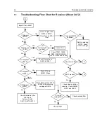
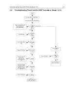
4.0
Troubleshooting Flow Chart for Synthesizer
+5V at
U3201 Pin’s
13 & 30?
5V
at pin 6 of
D3201
Is information
from
µP U0101
correct?
Is U3201
Pin 47
= 13VDC ?
Is U3301 Pin 19
<40 mVDC in RX &
>4.5 VDC in TX?
(at VCO section)
Start
Visual
check of the
Board OK?
Correct
Problem
Check 5V
Regulator
U3211
Is 16.8MHz
Signal at
U3201 Pin
19?
Check
Y3261, Y3263 and
associated Parts
Are signals
at Pin’s 14 &
15 of U3201?
Check
R3201
Check C3319
Is U3201 pin 2
>4.5 VDC in Tx &
<40 mVDC in Rx
Replace
U3201
Remove
Shorts
Is there a short
between Pin 47 and
Pins 14 & 15 of
U3201?
Replace or resolder
necessary components
Is RF level at
U3201 Pin 32
-12 < x <-25
dBm?
Are
R3221,
R3222, R3223,
C3221, C3222,
& C3224
OK?
Replace
U3201
If R3227, C3226 & C3227
are OK, then see VCO
troubleshooting chart
Are Waveforms
at Pins 14 & 15
triangular?
Do Pins
7,8 & 9 of
U3201 toggle
when channel is
changed?
Check programming
lines between U0101
and U3201 Pins 7,8 & 9
Replace
U3201
Check µP U0101
Troubleshooting
Chart
No
Yes
No
Yes
No
Yes
No
No
No
Yes
Yes
No
Yes
Yes
No
Yes
Yes
Yes
No
No
No
No
Yes
No
Yes
Yes
Check D3201,
C3202, C3203,
C3205 & C3206
5V at
U3201 pins 5,
20, 34 & 36
Check 5V
Regulator
U3211, R3211
Is
16.8MHz
signal at
U3201 pin
23?
Replace
U3201
Yes
No
No
Yes
No
Yes
Summary of Contents for 6864115B62-C
Page 1: ...Professional Radio GM Series Detailed Service Manual 6864115B62 C ...
Page 2: ...ii ...
Page 4: ...iv ...
Page 5: ...Professional Radio GM Series Service Maintainability Issue July 2007 ...
Page 8: ...ii ...
Page 22: ...2 10 MAINTENANCE ...
Page 25: ...Professional Radio GM Series Controlhead Service Information Issue July 2007 ...
Page 77: ...Professional Radio GM Series Controller Service Information Issue May 2007 ...
Page 100: ...2 2 TROUBLESHOOTING CHARTS ...
Page 104: ...3 4 Controller schematics parts list ...
Page 154: ...3 52 Controller T12 Schematic Diagrams ...
Page 155: ...Professional Radio GM Series VHF 136 174MHz Service Information Issue May 2007 ...
Page 164: ...1 6 MODEL CHART AND TECHNICAL SPECIFICATIONS ...
Page 176: ...2 12 THEORY OF OPERATION ...
Page 186: ...3 10 TROUBLESHOOTING CHARTS ...
Page 190: ...4 4 VHF PCB SCHEMATICS PARTS LISTS ...
Page 252: ...4 66 VHF 1 25W PCB 8471235L02 Schematics VHF 136 174 MHz IF ...
Page 256: ...4 70 VHF 1 25W PCB 8471235L02 Schematics ...
Page 257: ...Professional Radio GM Series UHF 403 470MHz Service Information Issue May 2007 ...
Page 266: ...1 6 MODEL CHART AND TECHNICAL SPECIFICATIONS ...
Page 366: ...2 12 THEORY OF OPERATION ...
Page 372: ...3 6 Low Band TROUBLESHOOTING CHARTS ...