


MOOG
ID
No.:
CB40859-001
Date:
02/2018
MSD Servo Drive - Device Help
132
7 Control
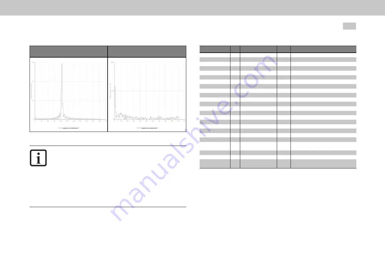
FFT without filtering
FFT with filtering
Table 7.14: FFT transformation
NOTE
Note that the filters not only have an effect on the amount but also
on the phase of the frequency response. At lower frequencies
higher-order filters (PT3, PT4) should not be used, as the phase
within the control bandwidth is negatively influenced.
The coefficients can also be specified directly via parameter
P 327
- CON_SCON_FilterPara
. They take effect directly, so changing
them is only recommended when the control is switched off.
A large bandwidth will result in a lower attenuation of the cut-off
frequency.
ID
Index Name
Unit
Description
325
325
0
Hz
325
1
Hz
325
2
Hz
325
3
Hz
326
0
327
CON_SCON_FilterFreq
CON_SCON_FilterFreq
CON_SCON_FilterFreq
CON_SCON_FilterFreq
CON_SCON_FilterFreq
CON_SCON_FilterAssi
CON_SCON_FilterPara
327
0
Filter frequencies of digital filter
1st center/cutoff
1st width
2nd center/cutoff
2nd width
Digital filter design assistant
Coefficients of digital filter
b0*x(k)
327
1
327
2
327
3
327
4
327
5
327
6
327
7
327
8
FilterPara b0
FilterPara b1
FilterPara b2
FilterPara b3
FilterPara b4
FilterPara a1
FilterPara a2
FilterPara a3
FilterPara a4
b1*x(k-1)
b2*x(k-2)
b3*x(k-3)
b4*x(k-4)
a1*y(k-1)
a2*y(k-2)
a3*y(k-3)
a4*y(k-4)
1550
0
1551
0
1552
1552
0
Hz
1552
1
SCD_NotchType
SCD_NotchCntl
SCD_NotchFreq
SCD_NotchFreq
SCD_NotchLambda
Hz/min^-
2
Adaptive Notch filter: Method
Adaptive Notch filter: Control word
Adaptive Notch filter: Frequencies
Adaptive Notch filter: Frequency
Adaptive Notch filter: Coefficient
1552
2
Hz
1552
3
Hz
1552
4
SCD_NotchMinFreq
SCD_NotchMaxFreq
SCD_NotchDeltaFreq
Hz
Adaptive Notch filter: Min. frequency
Adaptive Notch filter: Max. frequency
Adaptive Notch filter: Maximum frequency
change (in each iteration)
Table 7.15: “Speed controller - Digital filter” parameter
7.4.3 Analysis of Speed control
The speed controller is executed as a PI controller. The gain (P-component) and the
integral-action time (I-component) of the individual controllers are programmable.
In order to optimize the speed control loop, two rectangular reference steps are
preset. For automatic controller optimization the step response and transfer function
wizards are available.