


20 - 46
20. FA TRANSPARENT FUNCTION
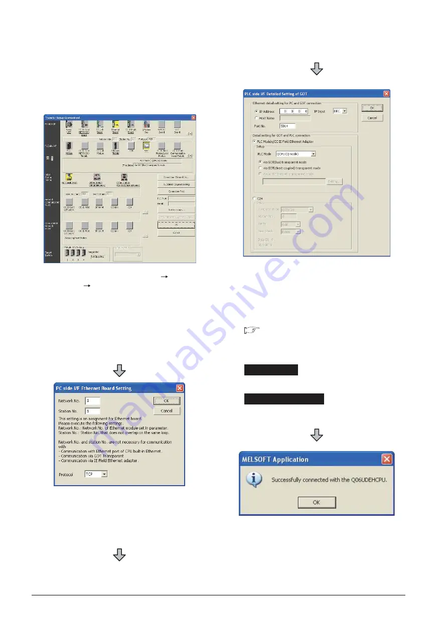
20.6 Personal Computer Side Setting
When connecting the GOT and the personal
computer by Ethernet
(1) Connecting the GOT and PLC in bus connection or
direct CPU connection (when connecting to QCPU
(Q mode))
1.
Click the Connection Destination view
[Connection
Destination]
[(Connection target data name)] in the
Navigation window of GX Works2.
2.
The [Transfer Setup] is displayed.
3.
Set the [Transfer Setup]:
PC side I/F :Ethernet Board
PLC side I/F :GOT
Other Station Setting : No specification
4.
Double-click [Ethernet Board] of the PC side I/F to
display [PC side I/F Ethernet Board Setting].
5.
Set the protocol to TCP. Network No. and Station No.
are not required to be changed (default) because they
are not used.
(For bus connection)
6.
Double-click [GOT] of the PLC side I/F to display
[PLC side I/F Detailed Setting of GOT].
7.
Set the IP address and port No. in [Ethernet detail
setting for PC and GOT connection].
Set the IP address and port No. to the same as the
Ethernet download setting.
20.5.1 (b) Ethernet download setting
8.
Check either of the followings in [Detail setting for
GOT and PLC connection].
[via GOT(Bus) transparent mode]
Mark the [via GOT(direct coupled) transparent mode]
checkbox.
9.
The screen returns to [Transfer Setup]. Click
[Connection Test] to check if GX Works2 has been
connected to the QCPU (Q mode).
Bus connection
Direct CPU connection
Summary of Contents for GOT2000 Series
Page 2: ......
Page 62: ...1 38 1 PREPARATORY PROCEDURES FOR MONITORING 1 6 Checking for Normal Monitoring ...
Page 64: ......
Page 80: ...2 16 2 DEVICE RANGE THAT CAN BE SET 2 6 MELSEC WS ...
Page 246: ...7 26 7 COMPUTER LINK CONNECTION 7 6 Precautions ...
Page 252: ...8 6 8 BUS CONNECTION 8 1 Connectable Model List ...
Page 256: ...8 10 8 BUS CONNECTION 8 2 System Configuration ...
Page 288: ...8 42 8 BUS CONNECTION 8 4 Precautions ...
Page 324: ...9 36 9 MELSECNET H CONNECTION PLC TO PLC NETWORK MELSECNET 10 CONNECTION PLC TO PLC NETWORK ...
Page 416: ......
Page 510: ...15 46 15 SERVO AMPLIFIER CONNECTION 15 7 Precautions ...
Page 518: ...16 8 16 ROBOT CONTROLLER CONNECTION 16 6 Precautions ...
Page 540: ...17 22 17 CNC CONNECTION 17 7 Precautions ...
Page 541: ...MULTIPLE GOT CONNECTIONS 18 GOT MULTI DROP CONNECTION 18 1 ...
Page 542: ......
Page 567: ...MULTI CHANNEL FUNCTION 19 MULTI CHANNEL FUNCTION 19 1 ...
Page 568: ......
Page 599: ...FA TRANSPARENT FUNCTION 20 FA TRANSPARENT FUNCTION 20 1 ...
Page 600: ......
Page 668: ...20 68 20 FA TRANSPARENT FUNCTION 20 7 Precautions ...
Page 670: ...REVISIONS 2 ...
Page 673: ......


