


4. HOW TO MONITOR REDUNTANT SYSTEM
4.2 Direct CPU Connection
4 - 13
4
HOW T
O
MONIT
O
R R
EDUNT
ANT SYSTEM
4.2.3
Precautions when connecting a GOT directly to a PLC CPU in the redundant
system without making Q redundant setting
(1)
As the GOT monitors exclusively the PLC CPU that is directly connected to, the monitor target cannot be
changed in response to the system switching of the redundant system.
To change the target monitor in response to the system switching, change the target of the connection cable
between the GOT and PLC CPU to the other PLC CPU, or configure the system using GOTs connected to each
PLC CPU.
(2)
In CPU direct connection, when monitoring a PLC CPU in the redundant system, only the PLC CPU that is
directly connected to the GOT can be monitored.
(3)
When connected to the standby system PLC CPU, the writing of the GOT to a device in the connected PLC
CPU is not reflected. Design a monitor screen that disables writing to the standby system.
In the redundant system, the tracking function transfers device data from control system to standby system.
When the tracking function is enabled, the device value of the standby system PLC CPU is overwritten by the
device value transferred from the control system to the standby system even if the GOT writes to the standby
system PLC CPU (Numerical input, Ascii input, Script, Recipe, or others).
As countermeasures to the above, perform the following.
• Display a monitor screen which indicates that "the connected PLC CPU is the standby system" on a GOT
when connecting the GOT to the standby system PLC CPU.
• To display the specified monitor screen when connecting the GOT to the standby system PLC CPU, use the
special relay SM1515 (Control status identification flag) of the PLC CPU.
(When the SM1515 is OFF, the connected PLC CPU is the standby system)
• Control the operation of each object by the SM1515, which is set for the operation condition.
• For the screen switching device, use a GOT internal device.
If a device of the PLC CPU is used, the trigger action operation of the GOT may be disabled since the device
data of the PLC CPU will is overwritten by the device value transferred with the redundant system tracking
function.
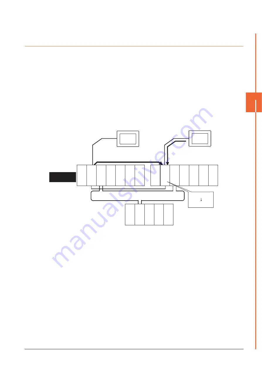
1) Numerically input D100=100
from the GOT.
1) D100=100
2) D100=5
2) Tracks D100=5 from control
system to standby system.
Power supply
module
Power supply
module
Power supply
module
MELSECNET/H remote I/O network
CPU direct connection
CPU direct connection
GOT1
Control system
(System A)
Empty
Empty
Empty
Empty
Q25PRHCPU
QJ71LP21-25
QJ71BR1
1
QJ71E71-100
QJ61BT1
1N
Standby system
(System B)
QJ72LP25-25
QJ71C24N
Q25PRHCPU
QJ71LP21-25
QJ71BR1
1
QJ71E71-100
QJ61BT1
1N
GOT2
Summary of Contents for GOT2000 Series
Page 2: ......
Page 62: ...1 38 1 PREPARATORY PROCEDURES FOR MONITORING 1 6 Checking for Normal Monitoring ...
Page 64: ......
Page 80: ...2 16 2 DEVICE RANGE THAT CAN BE SET 2 6 MELSEC WS ...
Page 246: ...7 26 7 COMPUTER LINK CONNECTION 7 6 Precautions ...
Page 252: ...8 6 8 BUS CONNECTION 8 1 Connectable Model List ...
Page 256: ...8 10 8 BUS CONNECTION 8 2 System Configuration ...
Page 288: ...8 42 8 BUS CONNECTION 8 4 Precautions ...
Page 324: ...9 36 9 MELSECNET H CONNECTION PLC TO PLC NETWORK MELSECNET 10 CONNECTION PLC TO PLC NETWORK ...
Page 416: ......
Page 510: ...15 46 15 SERVO AMPLIFIER CONNECTION 15 7 Precautions ...
Page 518: ...16 8 16 ROBOT CONTROLLER CONNECTION 16 6 Precautions ...
Page 540: ...17 22 17 CNC CONNECTION 17 7 Precautions ...
Page 541: ...MULTIPLE GOT CONNECTIONS 18 GOT MULTI DROP CONNECTION 18 1 ...
Page 542: ......
Page 567: ...MULTI CHANNEL FUNCTION 19 MULTI CHANNEL FUNCTION 19 1 ...
Page 568: ......
Page 599: ...FA TRANSPARENT FUNCTION 20 FA TRANSPARENT FUNCTION 20 1 ...
Page 600: ......
Page 668: ...20 68 20 FA TRANSPARENT FUNCTION 20 7 Precautions ...
Page 670: ...REVISIONS 2 ...
Page 673: ......


