


20 - 44
20. FA TRANSPARENT FUNCTION
20.6 Personal Computer Side Setting
6.
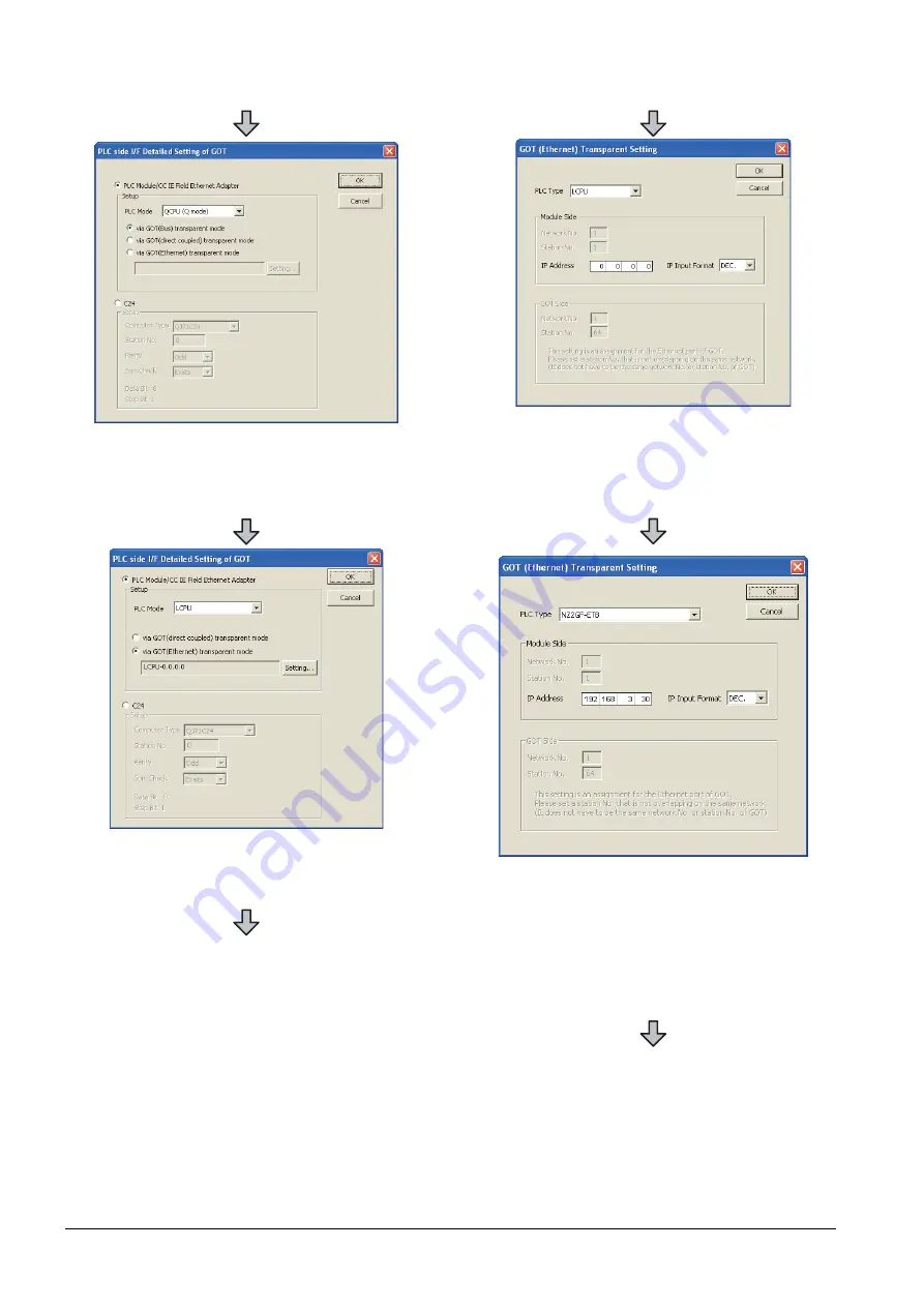
Double-click [GOT] of the PLC side I/F to display
[PLC side I/F Detailed Setting of GOT].
7.
Set the [CPU mode] to [LCPU].
8.
On the[PLC side I/F Detailed Setting of GOT], mark
the [via GOT(Ethernet) transparent mode] checkbox
and click [Setting...].
9.
[GOT (Ethernet) Transparent Setting] is displayed.
Here, set the Ethernet module, which is firstly
connected via a GOT.
10.
Set [NZ2GF-ETB] for [PLC Type].
11.
Set the same number to [IP address] as the number
assigned to NZ2GF-ETB, and click [OK].
In the system configuration example, the setting is as
follows.
[IP address]: 192 168 3 30
12.
Return to [PLC side I/F Detailed Setting of GOT], and
click [OK].
Summary of Contents for GOT2000 Series
Page 2: ......
Page 62: ...1 38 1 PREPARATORY PROCEDURES FOR MONITORING 1 6 Checking for Normal Monitoring ...
Page 64: ......
Page 80: ...2 16 2 DEVICE RANGE THAT CAN BE SET 2 6 MELSEC WS ...
Page 246: ...7 26 7 COMPUTER LINK CONNECTION 7 6 Precautions ...
Page 252: ...8 6 8 BUS CONNECTION 8 1 Connectable Model List ...
Page 256: ...8 10 8 BUS CONNECTION 8 2 System Configuration ...
Page 288: ...8 42 8 BUS CONNECTION 8 4 Precautions ...
Page 324: ...9 36 9 MELSECNET H CONNECTION PLC TO PLC NETWORK MELSECNET 10 CONNECTION PLC TO PLC NETWORK ...
Page 416: ......
Page 510: ...15 46 15 SERVO AMPLIFIER CONNECTION 15 7 Precautions ...
Page 518: ...16 8 16 ROBOT CONTROLLER CONNECTION 16 6 Precautions ...
Page 540: ...17 22 17 CNC CONNECTION 17 7 Precautions ...
Page 541: ...MULTIPLE GOT CONNECTIONS 18 GOT MULTI DROP CONNECTION 18 1 ...
Page 542: ......
Page 567: ...MULTI CHANNEL FUNCTION 19 MULTI CHANNEL FUNCTION 19 1 ...
Page 568: ......
Page 599: ...FA TRANSPARENT FUNCTION 20 FA TRANSPARENT FUNCTION 20 1 ...
Page 600: ......
Page 668: ...20 68 20 FA TRANSPARENT FUNCTION 20 7 Precautions ...
Page 670: ...REVISIONS 2 ...
Page 673: ......


