


20 - 32
20. FA TRANSPARENT FUNCTION
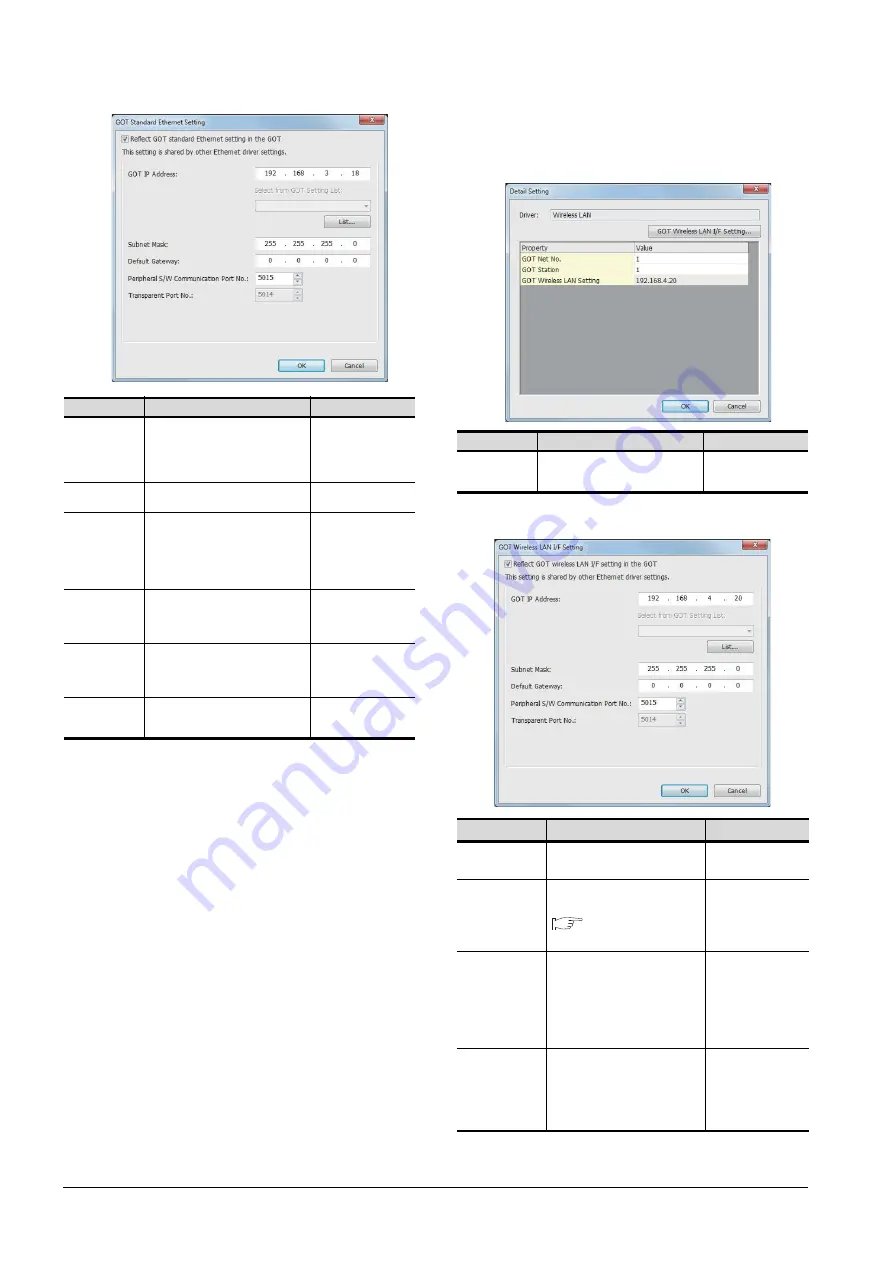
20.5 GOT Side Settings
(c) Wireless LAN setting
When communicating the GOT via wireless LAN,
set the interface of the GOT to be used in the
communication with the personal computer.
*1
Click the [GOT Wireless LAN I/F Setting] button and perform
the setting in the [GOT Wireless LAN I/F Setting] screen.
Item
Description
Range
GOT
IP Address
Set the IP address of the GOT.
(Default: 192.168.3.18)
When selecting the address from the
GOT setting list , click the [List] button
and select the GOT to be connected.
0.0.0.0 to
255.255.255.255
Select from
GOT Setting List
Select the set GOT in the [GOT
Setting List] dialog.
-
Subnet Mask
Set the subnet mask for the sub
network. (Only for connection via
router)
If the sub network is not used,
the default value is set.
(Default: 255.255.255.0)
0.0.0.0 to
255.255.255.255
Default
Gateway
Set the router address of the default
gateway where the GOT is connected.
(Only for connection via router)
(Default: 0.0.0.0)
0.0.0.0 to
255.255.255.255
Peripheral S/W
Communication
Port No.
Set the GOT port No. for the S/W
communication.
(Default: 5015)
1024 to 65534
(Except for 5011 to
5014 and 49153 to
49170)
Transparent
Port No.
Set the GOT port No. for the
transparent function.
(Default: 5014)
5014 (fixed)
Item
Description
Range
GOT Wireless
LAN I/F Setting
*1
Set the IP address of the GOT.
(Default: 192.168.4.20)
0.0.0.0 to
255.255.255.255
Item
Description
Range
GOT
IP Address
Set the IP address of the GOT.
(Default: 192.168.4.20)
0.0.0.0 to
255.255.255.255
Select from
GOT Setting List
Select the set GOT in the [GOT
Setting List] dialog.
GT Designer3
(GOT2000) Help
-
Subnet Mask
Set the subnet mask for the sub
network. (Only for connection
via router)
If the sub network is not used,
the default value is set.
(Default: 255.255.255.0)
0.0.0.0 to
255.255.255.255
Default
Gateway
Set the router address of the
default gateway where the GOT
is connected. (Only for
connection via router)
(Default: 0.0.0.0)
0.0.0.0 to
255.255.255.255
Summary of Contents for GOT2000 Series
Page 2: ......
Page 62: ...1 38 1 PREPARATORY PROCEDURES FOR MONITORING 1 6 Checking for Normal Monitoring ...
Page 64: ......
Page 80: ...2 16 2 DEVICE RANGE THAT CAN BE SET 2 6 MELSEC WS ...
Page 246: ...7 26 7 COMPUTER LINK CONNECTION 7 6 Precautions ...
Page 252: ...8 6 8 BUS CONNECTION 8 1 Connectable Model List ...
Page 256: ...8 10 8 BUS CONNECTION 8 2 System Configuration ...
Page 288: ...8 42 8 BUS CONNECTION 8 4 Precautions ...
Page 324: ...9 36 9 MELSECNET H CONNECTION PLC TO PLC NETWORK MELSECNET 10 CONNECTION PLC TO PLC NETWORK ...
Page 416: ......
Page 510: ...15 46 15 SERVO AMPLIFIER CONNECTION 15 7 Precautions ...
Page 518: ...16 8 16 ROBOT CONTROLLER CONNECTION 16 6 Precautions ...
Page 540: ...17 22 17 CNC CONNECTION 17 7 Precautions ...
Page 541: ...MULTIPLE GOT CONNECTIONS 18 GOT MULTI DROP CONNECTION 18 1 ...
Page 542: ......
Page 567: ...MULTI CHANNEL FUNCTION 19 MULTI CHANNEL FUNCTION 19 1 ...
Page 568: ......
Page 599: ...FA TRANSPARENT FUNCTION 20 FA TRANSPARENT FUNCTION 20 1 ...
Page 600: ......
Page 668: ...20 68 20 FA TRANSPARENT FUNCTION 20 7 Precautions ...
Page 670: ...REVISIONS 2 ...
Page 673: ......


