


20. FA TRANSPARENT FUNCTION
20.5 GOT Side Settings
20 - 31
20
F
A TRANSP
ARE
NT FU
NCTION
20.5 GOT Side Settings
20.5.1
Setting communication
interface
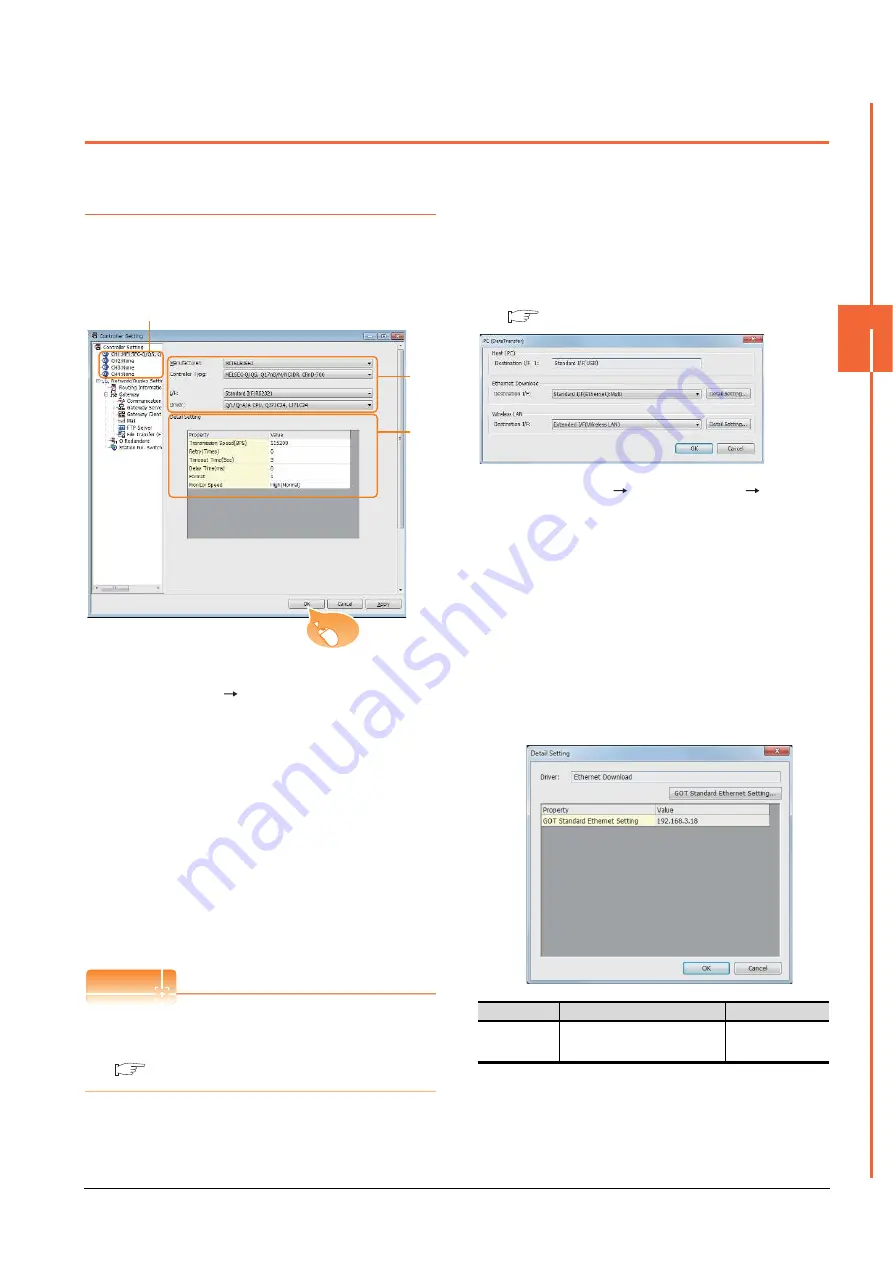
Controller setting
Set the channel of the connected equipment.
1.
Select [Common]
[Controller Setting] from the
menu.
2.
The Controller Setting window is displayed. Select the
channel to be used from the list menu.
3.
Set Manufacturer, Controller Type, I/F, and Driver
according to the connected equipment to be used.
4.
The detailed setting is displayed after Manufacturer,
Controller Type, I/F, and Driver are set.
Make the settings according to the usage
environment.
Click the [OK] button when settings are completed.
POINT
POINT
POINT
The settings of connecting equipment can be
confirmed in [I/F Communication Setting].
For details, refer to the following.
1.1.2 I/F communication setting
Communication setting with personal
computer
Set the communication setting between the GOT and the
personal computer.
For details of the setting contents, refer to the following
manual.
GT Designer3 (GOT2000) Help
1.
Select [Common]
[Peripheral Setting]
[PC(Data
Transfer) ]from the menu.
2.
The [PC (Data Transfer)] is displayed. Set the
interface of the GOT to be used in the communication
with the personal computer.
(a) Host (PC) setting
When communicating the GOT and the personal
computer in the direct connection, set the interface
of the GOT to be used in the communication with
the personal computer.
(b) Ethernet download setting
When communicating the GOT via Ethernet, set
the interface of the GOT to be used in the
communication with the personal computer.
*1
Click the [GOT Standard Ethernet Setting] button and
perform the setting in the [GOT Standard Ethernet Setting]
screen.
2.
3.
4.
Click!
Item
Description
Range
GOT Standard
Ethernet Setting
*1
Set the IP address of the GOT.
(Default: 192.168.3.18)
0.0.0.0 to
255.255.255.255
Summary of Contents for GOT2000 Series
Page 2: ......
Page 62: ...1 38 1 PREPARATORY PROCEDURES FOR MONITORING 1 6 Checking for Normal Monitoring ...
Page 64: ......
Page 80: ...2 16 2 DEVICE RANGE THAT CAN BE SET 2 6 MELSEC WS ...
Page 246: ...7 26 7 COMPUTER LINK CONNECTION 7 6 Precautions ...
Page 252: ...8 6 8 BUS CONNECTION 8 1 Connectable Model List ...
Page 256: ...8 10 8 BUS CONNECTION 8 2 System Configuration ...
Page 288: ...8 42 8 BUS CONNECTION 8 4 Precautions ...
Page 324: ...9 36 9 MELSECNET H CONNECTION PLC TO PLC NETWORK MELSECNET 10 CONNECTION PLC TO PLC NETWORK ...
Page 416: ......
Page 510: ...15 46 15 SERVO AMPLIFIER CONNECTION 15 7 Precautions ...
Page 518: ...16 8 16 ROBOT CONTROLLER CONNECTION 16 6 Precautions ...
Page 540: ...17 22 17 CNC CONNECTION 17 7 Precautions ...
Page 541: ...MULTIPLE GOT CONNECTIONS 18 GOT MULTI DROP CONNECTION 18 1 ...
Page 542: ......
Page 567: ...MULTI CHANNEL FUNCTION 19 MULTI CHANNEL FUNCTION 19 1 ...
Page 568: ......
Page 599: ...FA TRANSPARENT FUNCTION 20 FA TRANSPARENT FUNCTION 20 1 ...
Page 600: ......
Page 668: ...20 68 20 FA TRANSPARENT FUNCTION 20 7 Precautions ...
Page 670: ...REVISIONS 2 ...
Page 673: ......


