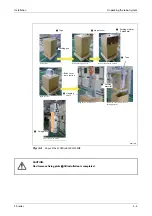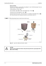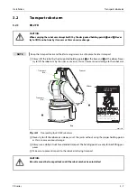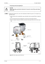
Set up the robot arm
Installation
3 - 16
3.3
Set up the robot arm
3.3.1
Set up the articulated arm robot
RV-2FR/4FR/7FR/7FRLLM/13FR/20FR
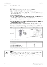
The table below shows how to set up and fix the articulated arm robots RV-2FR/4FR/7FR/7FRLLM/
13FR/20FR.
The base area of the robot arm has been levelled by machine.
If the base area is too uneven then this may result in robot arm malfunctions.
Fix the robot arm above the assembly boreholes on the four outer edges of the base area using
the supplied Allen head screws.
Align the robot arm horizontally.
The average surface finish of the assembly surface should be Ra = 6.3 μm. If the surface is too
rough then this may result in deviations in the position of the robot arm.
To avoid position deviations, the peripheral equipment that the robot accesses as well as the robot
arm itself should be installed on a common assembly platform/area.
The base area must be designed so that no distortion can occur, even from the loads and
vibrations emanating from the robot itself.
Only remove the transport locks after setting up the robot arm.
If the robot is mounted on the ceiling then the MEGDIR parameter must be changed. Additional
information on this parameter is contained in the operation and programming instructions of the
controllers.
High loads and strains occur on the base area when operating the robot at high speeds. Make
sure that the base area is suitable for the high forces and moments, as listed in Tab. 3-2.
Robot arm
Fixture
View from below
RV-2FR
R002690E
R002691E
RV-4FR
R002690E
R002692E
Tab. 3-1:
Set up the robot arm (1)
Fixing
screws (4)
M8 x 35 Allen screw
Snap ring
Washer
In
stall
a
tion
si
de
Installation side
Front side of the
robot arm
4-
∅
9 fixing boreholes
Fixing
screws (4)
M8 x 40 Allen screw
Snap ring
Washer
In
sta
lla
tion
si
de
Installation side
Front side of the
robot arm
4-
∅
9 fixing boreholes
Summary of Contents for MELFA RH-FRH-D
Page 2: ......
Page 4: ......
Page 6: ......
Page 16: ...Contents X ...
Page 22: ...Environmental conditions for operation Introduction 1 6 ...
Page 70: ...Grounding the robot system Installation 3 32 ...
Page 90: ...Teaching Box connection Connection 4 20 ...
Page 96: ...Switch on the robot system Startup 5 6 ...
Page 128: ...Dimensions Appendix A 18 ...
Page 130: ...A 20 Index Appendix ...
Page 131: ......
Page 132: ......
Page 133: ......
Page 134: ......
Page 135: ......
Page 136: ......
Page 137: ......
Page 138: ......
Page 139: ......
Page 140: ......
Page 141: ......
Page 142: ......
Page 143: ......
Page 144: ......
Page 145: ......
Page 146: ......
Page 147: ......
Page 148: ......
Page 149: ......
Page 150: ......
Page 151: ......
Page 152: ......
Page 153: ......
Page 154: ......
Page 155: ......
Page 156: ......
Page 157: ......
Page 158: ......
Page 159: ......
Page 160: ......
Page 161: ......
Page 162: ......
Page 163: ......
Page 164: ......
Page 165: ......


