Dimensions
Appendix
A - 12
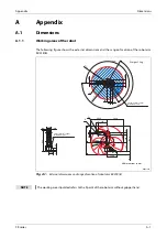
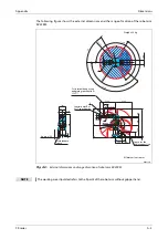
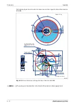
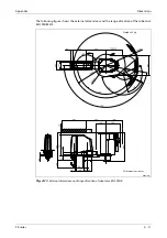
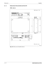
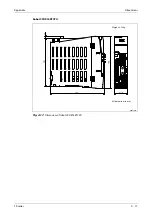
The following figure shows the external dimensions and the range of motion of the robot arm
RH-3FRHR3515/3512.
Installation platform is prepared by customer.
R002747E
Fig. A-12:
External dimensions and range of motion of robot arm RH-3FRHR3515/12
175
175
(180)
195
420
11
5
360
340
180
160
135
124
112
135
112
Rz25
Rz25
(90)
225°
225°
225°
225°
R175
(80)
53
336
310
R252.5
230
300
500
R350
246
A
170
A
B
Weight: 24 kg
All dimensions in mm
No.1 arm rotation radius
Installation
surface
Robot origin
2-M12 suspension hole
4-M8 jack-up hole
4-Ø9 installation hole
Installation reference
In
sta
lla
ti
on r
e
fer
e
nce
Robot
A
B
RH-3FRHR3515
583
150
RH-3FRHR3512C
613
120
Summary of Contents for MELFA RH-FRH-D
Page 2: ......
Page 4: ......
Page 6: ......
Page 16: ...Contents X ...
Page 22: ...Environmental conditions for operation Introduction 1 6 ...
Page 70: ...Grounding the robot system Installation 3 32 ...
Page 90: ...Teaching Box connection Connection 4 20 ...
Page 96: ...Switch on the robot system Startup 5 6 ...
Page 128: ...Dimensions Appendix A 18 ...
Page 130: ...A 20 Index Appendix ...
Page 131: ......
Page 132: ......
Page 133: ......
Page 134: ......
Page 135: ......
Page 136: ......
Page 137: ......
Page 138: ......
Page 139: ......
Page 140: ......
Page 141: ......
Page 142: ......
Page 143: ......
Page 144: ......
Page 145: ......
Page 146: ......
Page 147: ......
Page 148: ......
Page 149: ......
Page 150: ......
Page 151: ......
Page 152: ......
Page 153: ......
Page 154: ......
Page 155: ......
Page 156: ......
Page 157: ......
Page 158: ......
Page 159: ......
Page 160: ......
Page 161: ......
Page 162: ......
Page 163: ......
Page 164: ......
Page 165: ......

