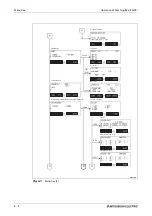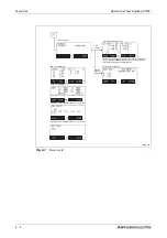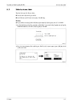
Move robot in JOG mode
Operation of Teaching Box (R32TB)
6 - 10
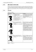
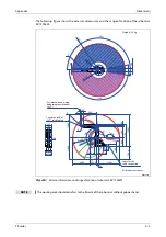
3-axis XYZ JOG mode
R002735E
Execute the three points listed above.
l
Press the function key twice to switch to the
3-axis XYZ JOG mode.
The position of the tipped tool can be moved
along the axes in the XYZ coordinate system in
3-axis XYZ JOG mode.
In contrast to XYZ JOG mode, the position of
the robot is changed as in articulated joint
mode by rotating axes J4, J5 and J6. With a
fixed position of the tipped too, the position is
interpolated over axes X, Y, Z, J4, J5 and J6, i.e.
the position is not constant.
The middle point of the tool must be set by
parameter MEXTL.
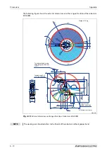
Circle JOG mode
R002736E
Execute the three points listed above.
l
Press the function key three times to switch
to the circle JOG mode.
The position of the tipped tool can be rotated
in circles around the zero point in circle JOG
mode.
A change in the X-axis coordinate moves the
tipped tool radially, starting from the middle
point of the robot. A change in the Y-axis coor-
dinate has the effect of the same movement
as control of the J1 axis in articulated joint JOG
mode. A change in the Z-axis coordinate has
the effect of a manual movement in the Z
direction as in XYZ JOG mode.
If the coordinates of the A, B or C axis are
changed then the hand gripper is rotated as in
XYZ JOG mode. The axes of robot type RH can
be controlled.
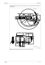
Workpiece jog mode
R002737E
Execute the three points listed above.
l
Press the function key three times to switch
to workpiece JOG mode.
l
To move the axes, press appropriate key X,
Y, Z, A, B, C.
In workpiece jog mode, the position of the
tipped tool can be moved along the axles of
the workpiece coordinate system. Buttons A, B
and C rotate the position of the robot around
the X, Y and Z axles of the workpiece coor-
dinate system without changing the position
of the tipped tool. You must set the tool mid-
dle point with the MEXTL parameter.
NOTE:
Workpiece coordinate system:
You must set the workpiece coordinate sys-
tem before using JOG mode. (There are eight
parameters (WKnCORD, n = 1 - 8) for setting
the coordinate system.) If the workpiece coor-
dinate system is not defined, the robot will
move in XYZ JOG mode. For details please
consult the robot’s technical manual.
NOTE
If the monitoring point of the hand in tool JOG mode, XYZ JOG mode or circle JOG mode
approaches a singular point then a warning sign appears on the Teaching Box and a warning sig-
nal is issued. The function can be deactivated by parameter MESNGLSW. A detailed description of
the parameter and the function "Error message on reaching a singular point" is contained in the
operating and programming instructions.
Operating mode
Mode
Description
Tab. 6-1:
JOG modes (2)
+J6
-J6
-J5
+J5
+J4
-J4
+X
+Y
+Z
+X
+C
-C
+Z
+Y
-Y
-A
+A
+Y
+B
-B
+Z
+Y
+X
Z
Y
X
Workpiece
coordinates
Summary of Contents for MELFA RH-FRH-D
Page 2: ......
Page 4: ......
Page 6: ......
Page 16: ...Contents X ...
Page 22: ...Environmental conditions for operation Introduction 1 6 ...
Page 70: ...Grounding the robot system Installation 3 32 ...
Page 90: ...Teaching Box connection Connection 4 20 ...
Page 96: ...Switch on the robot system Startup 5 6 ...
Page 128: ...Dimensions Appendix A 18 ...
Page 130: ...A 20 Index Appendix ...
Page 131: ......
Page 132: ......
Page 133: ......
Page 134: ......
Page 135: ......
Page 136: ......
Page 137: ......
Page 138: ......
Page 139: ......
Page 140: ......
Page 141: ......
Page 142: ......
Page 143: ......
Page 144: ......
Page 145: ......
Page 146: ......
Page 147: ......
Page 148: ......
Page 149: ......
Page 150: ......
Page 151: ......
Page 152: ......
Page 153: ......
Page 154: ......
Page 155: ......
Page 156: ......
Page 157: ......
Page 158: ......
Page 159: ......
Page 160: ......
Page 161: ......
Page 162: ......
Page 163: ......
Page 164: ......
Page 165: ......

