Set up the robot arm
Installation
3 - 20
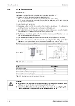
General environment type: 180 mm
Clean/waterproof specification: 200 mm
The interference of installation bolt and No.1 arm may occur depending on the size of installation
stage. Take care against interference of installation bolt, such as inserting the installation bolt
from the bottom.
R002700E
Fig. 3-14:
Set up the robot arm
Load
RH-3FRHR
Moment of tilt M
L
[Nm]
380
Torsional moment M
T
[Nm]
410
Translational forces on horizontal plane F
H
[N]
920
Translational forces on vertical plane F
V
[N]
570
Tab. 3-5:
Reaction forces on the base area of the robot
㻲
㼂
㻹
㼀
㻲
㻴
㻹
㻸
㻲
㻴
㻹
㻸
㻲
㻴
㻲
㻴
㻲
㼂
Installation side
(standard)
4-
∅
9 fixing boreholes
2-M12 hole for hanging tool
4-M8 hole to jack-up
Installation stage
(example)
Maintenance space
In
stall
a
ti
on
side
(s
tan
d
ar
d)
Maintenance space
Summary of Contents for MELFA RH-FRH-D
Page 2: ......
Page 4: ......
Page 6: ......
Page 16: ...Contents X ...
Page 22: ...Environmental conditions for operation Introduction 1 6 ...
Page 70: ...Grounding the robot system Installation 3 32 ...
Page 90: ...Teaching Box connection Connection 4 20 ...
Page 96: ...Switch on the robot system Startup 5 6 ...
Page 128: ...Dimensions Appendix A 18 ...
Page 130: ...A 20 Index Appendix ...
Page 131: ......
Page 132: ......
Page 133: ......
Page 134: ......
Page 135: ......
Page 136: ......
Page 137: ......
Page 138: ......
Page 139: ......
Page 140: ......
Page 141: ......
Page 142: ......
Page 143: ......
Page 144: ......
Page 145: ......
Page 146: ......
Page 147: ......
Page 148: ......
Page 149: ......
Page 150: ......
Page 151: ......
Page 152: ......
Page 153: ......
Page 154: ......
Page 155: ......
Page 156: ......
Page 157: ......
Page 158: ......
Page 159: ......
Page 160: ......
Page 161: ......
Page 162: ......
Page 163: ......
Page 164: ......
Page 165: ......

