Connection
EMERGENCY-STOP connection
FR series
4 - 11
4.3.2 CR800
controller
E
CAUTION:
Do not carry out a surge voltage test.
R002722E
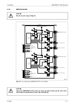
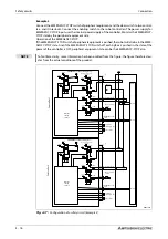
Fig. 4-11:
Internal wiring of EMERGENCY-STOP circuit (CR800)
E
CAUTION:
Connect the EMERGENCY-STOP switch at an easily accessible location near the robot. If the
robot behaves erratically then you must stop it immediately.
Controller
Customer
Customer
Output for
operating mode
Control
circuit 1
Error
output
EMERGENCY-STOP switch
Door closing contact
EMERGENCY-STOP Teaching Box
EMERGENCY-STOP
output
Control
circuit 2
Mode
output
Robot error
output
EMERGENCY-STOP
output
Mode selector switch
EMERGENCY-STOP switch
Door closing contact
Mode selector switch
+24 V
+3,3 V
+3,3 V
+24 V
+24 V
+24 V
+24 V
+24 V
+24 V
+24 V
+3,3 V
+3,3 V
+24 V
+3,3 V
+3,3 V
+3,3 V
+3,3 V
+3,3 V
+3,3 V
+3,3 V
+3,3 V
Summary of Contents for MELFA RH-FRH-D
Page 2: ......
Page 4: ......
Page 6: ......
Page 16: ...Contents X ...
Page 22: ...Environmental conditions for operation Introduction 1 6 ...
Page 70: ...Grounding the robot system Installation 3 32 ...
Page 90: ...Teaching Box connection Connection 4 20 ...
Page 96: ...Switch on the robot system Startup 5 6 ...
Page 128: ...Dimensions Appendix A 18 ...
Page 130: ...A 20 Index Appendix ...
Page 131: ......
Page 132: ......
Page 133: ......
Page 134: ......
Page 135: ......
Page 136: ......
Page 137: ......
Page 138: ......
Page 139: ......
Page 140: ......
Page 141: ......
Page 142: ......
Page 143: ......
Page 144: ......
Page 145: ......
Page 146: ......
Page 147: ......
Page 148: ......
Page 149: ......
Page 150: ......
Page 151: ......
Page 152: ......
Page 153: ......
Page 154: ......
Page 155: ......
Page 156: ......
Page 157: ......
Page 158: ......
Page 159: ......
Page 160: ......
Page 161: ......
Page 162: ......
Page 163: ......
Page 164: ......
Page 165: ......

