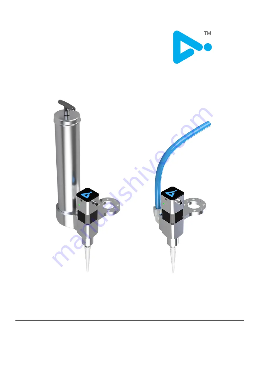
FD400 & FDhighV
USER MANUAL
AIM
ROBOTICS
ORIGINAL INSTRUCTIONS (EN) VERSION 0.4
Page 1: ...FD400 FDhighV USER MANUAL AIM ROBOTICS ORIGINAL INSTRUCTIONS EN VERSION 0 4 ...
Page 2: ...WRITTEN APPROVAL BY AIM ROBOTICS APS THE INFORMATION IS SUBJECT TO CHANGES WITHOUT NOTICE AND SHOULD NOT BE CONSTRUED AS A COMMITMENT BY AIM ROBOTICS APS THIS MANUAL WILL PERIODICALLY REVIEWED AND REVISED AIM ROBOTICS APS ASSUME NO RESPONSIBILITY FOR ANY ERRORS OR OMISSIONS IN THIS DOCUMENT COPYRIGHT C 2020 2021 BY AIM ROBOTICS APS ...
Page 3: ...S IN THE BOX INSTALLATION OPERATIONS GUIDE SOFTWARE CONFIGURATION PROGRAMMING Dispensing Node Auto TCP Circles Waves Pre feed Node Installation Node Purge Cycle Purge Node SAFETY HOW TO FAQ CERTIFICATION EU DECLARATION OF INCORPORATION 1 2 3 4 5 8 9 11 11 11 12 13 14 15 16 17 19 19 20 ...
Page 4: ...LED INDICATOR D ROD TAB PUMP UNIT CARTRIDGE BARREL ROD HANDLE FLUID FUNNEL WHAT S IN THE BOX 1 E A C B a FD400 3 X NOZZLES 8PIN LEAD USB WITH URCAP 6xM6 SCREW 1x ORIENTATION PIN ...
Page 5: ...omponent medium viscosity fluids NLGI class 2 3 FD400 FEATURES Model FD400 URCap version 3 0 Mechanical interface ISO 9409 1 type 50 4 M6 Electrical interface 8 pole M8 Digital interfaces URCap PolyScope 5 5 URCap API 1 8 RS485 24V I O Weight without cartridge 1 7kg Dimensions 135 x 145 x 390mm TECHNICAL DATA FD400 ...
Page 6: ...3 X NOZZLES 8PIN LEAD WHAT S IN THE BOX 3 USB WITH URCAP LED INDICATOR D PUMP UNIT NPT 1 4 INLET F C FDhighV 6xM6 SCREW 1x ORIENTATION PIN ...
Page 7: ...mponent medium to high viscosity fluids FDhighV FEATURES Model FDhighV URCap version 3 0 Mechanical interface ISO 9409 1 type 50 4 M6 NPT 1 4 Electrical interface 8 pole M8 Digital interfaces URCap PolyScope 5 5 URCap API 1 8 RS485 24V I O Weight 0 8kg Dimensions 65 x 130 x 170mm FDhighV ...
Page 8: ... cartridge Screw cartridge barrel into funnel E Release the rod handle by pulling it back and pressing the tab a The rod is now fully inserted into the fluid and the handle is fully against the barrel On the cartridge remove back lid Attach unit to robot flange with 4 screws 1 Assemble unit and attach to robot Attach funnel E with 2 screws 5 2 Load cartridge 400m l DIN 1284 FD400 ...
Page 9: ... unit to the robot so that it does not create a risk The pin can be inserted for orientation Attach NPT1 4 connector with feeding line to inlet F While the robot is off or tool I O is zero Plug in the 8 pin connector into unit and robot Assemble unit and attach to robot Attach unit to robot flange with 4 screws FDhighV 6 LED indicator D The unit has a LED indicator When the unit has power a steady...
Page 10: ...ndle and angle it to keep it extended Insert cartridge into barrel 7 Attach barrel into funnel E Release rod handle from ledge It will stay extended Adapt FD400 to use 310ml cartridges Screw adaptor on to the cartridge Cut tip off cartridge ...
Page 11: ...on to collect the fluid dispensed Use this position to purge the unit at cartridge refill at pause or at end of shift This is an operator defined position which is where the robot will know it can dispense if the Purge Cycle has been activated Press Hold to dispense When using a new cartridge or after a pause then it is recommended to purge the system Press Hold the button to dispense fluid contin...
Page 12: ...P Payload and Centre of Gravity and press the wizard button or enter manually unit itself weight of cartridge To define Tool Centre Point TCP select General TCP Tool Center Point and press the wizard button SOFTWARE CONFIGURATION 2 Payload and TCP 9 1 Install URCap Multiple URCaps If multiple URCaps are installed the tool might not perform as intended Some tools are programmed to takeover and cont...
Page 13: ... URCap In the IO interface control section use pull down menu to select User Change Tool Output Voltage to 24 The Tool IO can be controlled by the Aim URCap The Tool IO can be controlled by user and manually entered You are now ready to start programming your unit to start dispensing SOFTWARE CONFIGURATION 3 Unit Installation ...
Page 14: ...ging from the nozzle after dispensing Activate Run with Dispensing when path is tested and ready for dispensing Auto TCP speed ensures the dispensing speed varies with the robot speed It is disabled as default It it possible to multiply the dispensing speed for thicker lines To enable Auto TCP speed press the Enable button Programming the unit PROGRAMMING Aim Dispense Node Maintaining the same dis...
Page 15: ...dius and select Center Point to define the center of the circle After entering the Robot speed and Robot Acceleration press Move to start This will be the point where the robots starts dispensing the circle Consider the run up to this point when programming Programming CIRCLES 12 PROGRAMMING Radius Centre point ...
Page 16: ...d Enter Wave Count amount of waves between start and end point Enter Wave Width Press Add Start End to select the start and end point of the line for the wave to follow Programming WAVES The wave curve is also dependant on the robots movements Wave count Start End Wave width 13 PROGRAMMING ...
Page 17: ... nozzle In order for the next path to start dispensing at the start point defined the PreFeed will start the dispensing the just before the path starts to ensure the fluid is ready at the tip of the nozzle for a smooth start PROGRAMMING Aim Pre Feed Node 14 Fluid out of tip Fluid after PullBack Fluid after PreFeed ...
Page 18: ...ram and only runs if the program is stopped and positioned over the Purge Position This can be useful if the unit has to stand for a longer period of time Use Set Purge Position to define the position the robot has to been in when purging cleaning Use Press and Hold to Dispense to dispense the fluid at startup to fill system PROGRAMMING Aim Installation Node Purge Cycle 15 Purge Position Dispenses...
Page 19: ...e the tip The parameters and the Purge Point must be defined in the Purge Node Select Purge Point in the program tree This node will run in the program tree if inserted If a Halt command is added at Purge Position and the Clean Cycle is active the cleaning cycle will start PROGRAMMING Aim Purge Node 16 ...
Page 20: ...ns in Installation Safety Robot Limits reduce limits to ensure greater safety so that the robot will stop dispensing if it exceeds these limits Take care when inserting removing releasing the handle on the container as the spring might release the container from the unit with great force Hold on tight Ensure the container is correctly fitted to unit before releasing the handle to avoid it falling ...
Page 21: ...possible lock degrees of freedom in safety system Can happen when moving between work units or between separate dispensing paths AVOID Entrapment of fingers limbs If possible select the right low torque force settings in the safety system of the robot Whenever possible limit rotational range of joint 6 Rotate a low speeds or when clearance to robot links are small Where possible ensure minimum gap...
Page 22: ... avoid interference Restart Ensure that restart has been done after installation and LED light is a steady green FAQ Tool IO Power must be zero when plugging in the end effector Select the Installation tab and select General Tool IO Set Tool IO to zero 19 The unit does not dispense ...
Page 23: ......
Page 24: ...AIM ROBOTICS ORIGINAL INSTRUCTIONS EN VERSION 0 4 DESIGNED IN DENMARK BY AIM ROBOTICS APS AIM ROBOTICS COM CONTACT AIM ROBOTICS COM ...