Trio™ Operating Instructions
0070-10-0666-01
2 - 19
Operations
Parameter Menus
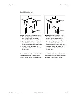
Lead II Monitoring
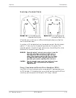
FIGURE 2-20
Lead II Monitoring (AHA)
FIGURE 2-21
Lead II Monitoring (IEC)
• Place the RA (white) electrode under the
patient’s right clavicle, at the mid-
clavicular line within the rib cage frame.
• Place the LA (black) electrode under the
patient’s left clavicle, at the mid-
clavicular line within the rib cage frame.
• Place the LL (red) electrode on the
patient’s lower left abdomen within the
rib cage frame.
Select ECG Lead II on the monitor. Lead II is
the direct electrical line between the RA
(white) electrode and the LL (red) electrode.
• Place the R (red) electrode under the
patient’s right clavicle, at the mid-
clavicular line within the rib cage frame.
• Place the L (yellow) electrode under the
patient’s left clavicle, at the mid-
clavicular line within the rib cage frame.
• Place the F (green) electrode on the
patient’s lower left abdomen within the
rib cage frame.
Select ECG Lead II on the monitor. Lead II is
the direct electrical line between the R (red)
electrode and the F (green) electrode.
White
Black
Red
Red
Yellow
Green
R
L
F

