


INSTALLING THE M204 ON THE NETWORK: Connecting Peripherals
17
als on page 17 for details on each of the M204’s I/O ports.
3
Unpack and plug in the power supply. The connector plugs into the back of the
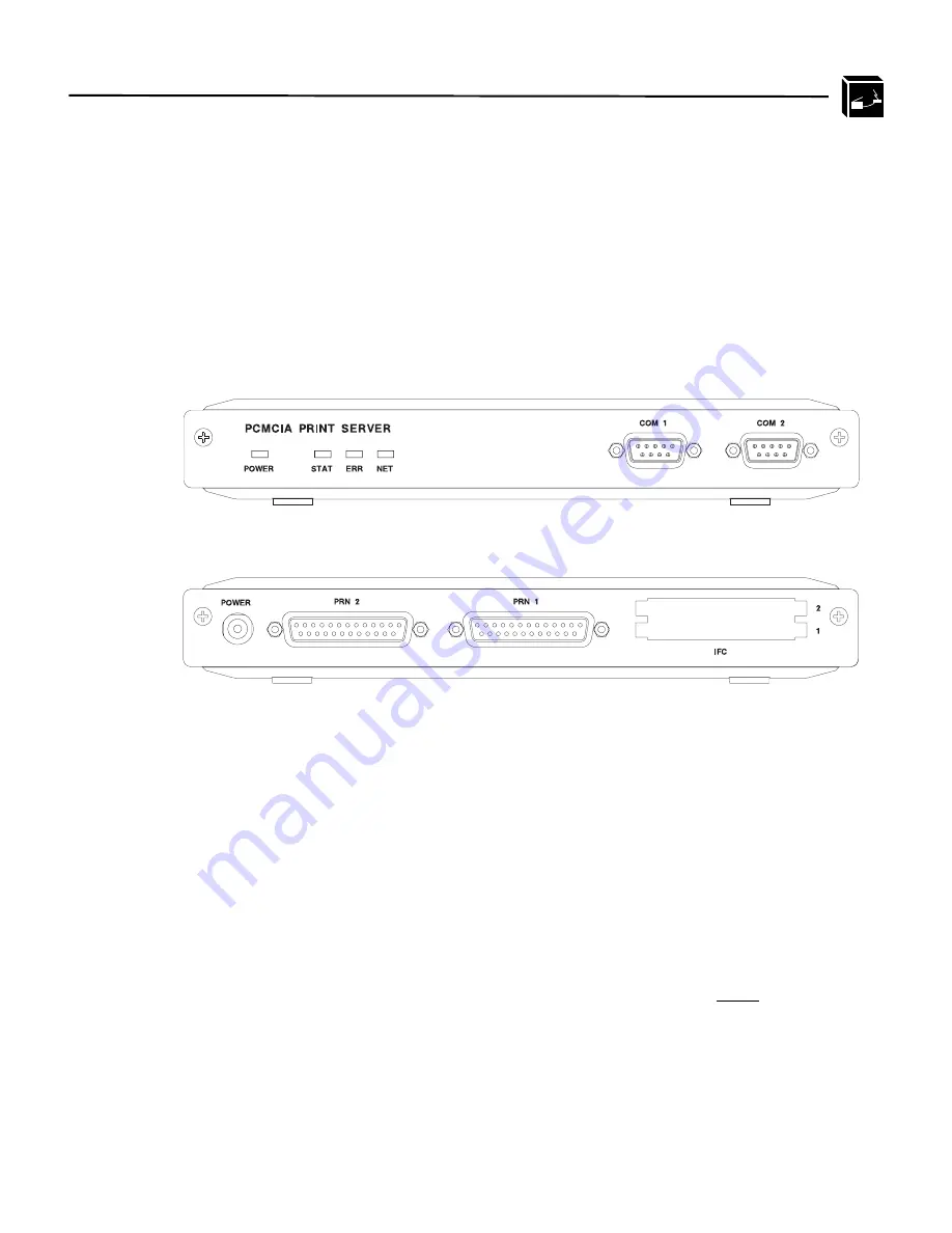
M204. Watch the lights on the front panel of the Print Server as they cycle through
the power-on self test. When the self test is complete, the POWER light is on and
STAT is flashing.
Figure 2:
M204 Diagram
Connecting Peripherals
A maximum of four devices can be attached to an M204 at the same time; two on the
parallel ports and two on the serial ports.
Parallel Port Connections (PRN1, PRN2)
Two 25-pin female DB-25S connectors with an IBM PC compatible pinout are pro-
vided on the rear panel for connection to a printer using a parallel port. These ports
can be configured with various parameters depending on the attached printer. These
parameters include:
•
ackmode for printers (usually non-laser printers) that use the ACK signal for the
trigger of next data transfer rather than the BUSY signal,
M204 Front View
M204 Rear View
Summary of Contents for M204
Page 8: ...vi LIST OF TABLES...
Page 12: ...4 PREFACE Computer Entry and Display Conventions...
Page 22: ...14 GETTING TO KNOW THE M204 Overview of Print Server Installation...
Page 70: ...62 CONFIGURING THE M204 FOR NOVELL Host Configuration...
Page 124: ...116 USING NPWIN Starting a NPWin Session With An Unconfigured Unit...
Page 125: ...117...
Page 126: ...118...
Page 154: ...146 USING THE M204 S ADDITIONAL OPTIONS IP Routing...
Page 166: ...156 TROUBLESHOOTING THE M204 Windows Problems...
Page 192: ...182 GLOSSARY B A C...
Page 196: ...186 APPENDIX A Planning Your Print Setup...
Page 204: ...194 INDEX...


