48
BA023001-en
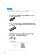
Installation process
NOTICE
First, carefully place the connectors on the IFM sockets and turn them until the holes
snap onto the pins. Only then push the connector on completely.
1
Pull the required cables from the roller set through the empty conduit provided by
the customer with the cable ends cut off in the direction of the control box.
2
Connect the two motor cables directly to the couplings provided on the motor
until the plug connection engages.
3
Pull off the protective cap from X1 on the IFM. Carefully plug the CAN data cable
with the M12 connector onto the and tighten the locking ring on the connector by
turning it clockwise.
4
Attach the cable lug of the protective conductor single wire by means of M6
screw, washer and contact/toothed lock washer to the threaded hole with
attached protective conductor marking in the roller set.
Summary of Contents for CONNECT Series
Page 19: ...19 BA023001 en 2 3 2 Set up diagram Set up diagram I ...
Page 20: ...20 BA023001 en Set up diagram II ...
Page 22: ...22 BA023001 en 2 4 1 Wiring diagram ...
Page 23: ...23 BA023001 en 2 4 2 Control cabinet structure Basic variant ...
Page 24: ...24 BA023001 en 2 4 3 Control cabinet structure Full equipment ...
Page 25: ...25 BA023001 en ...
Page 53: ...53 BA023001 en ...
Page 138: ...138 BA023001 en 13 Annex 13 1 Naming convention ...


