132
BA023001-en
11.5
Radio remote control RECO S
11.5.1
Description
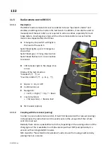
The RECO S radio remote control is considered to be an "operator's station" and
enables presettings to be made in the test bench. In addition, it can also be used to
manually start the test rollers, as is required in some countries, especially for truck
brake testers. An emergency stop switch on the remote control ensures that the
motors are stopped safely at all times.
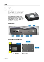
A
Emergency stop switch with light in
the head of the switch
Switch head lights up red = Emergency
stop active
Switch head grey = Emerg. stop inactive
Switch head flashes red = no connection
to receiver
B
LED indicator light in the shape of an
arrow
Display of the test direction:
"Standard" (↑
↑) or
"Counter-rotation
" (↑
↓ or ↓
↑)
C
Motor: I = On, 0 = Off
D
Confirmation: ok
E
Navigation:
< = Left, > = Right, ˄ = Up, ˅ = Down
F
Load simulation:
+ = Increase load, - = Reduce load
G
NFC reader (option)
11.5.2
Coupling with the receiver (pairing)
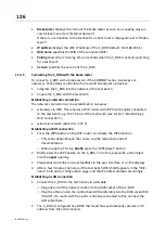
In order to use a radio remote control, it must first be paired with a receiver (pairing).
In the process the radio channel to be used is set and the unique ID of the remote
control is read out.
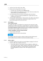
Basically there are two possibilities to do this, depending on the existing version of the
charging box. This is available in a simple version (without NFC) and optionally in a
version with an integrated NFC reader.
NFC stands for "Near Field Communication" and is known from using credit cards by
placing them on a reader.
A
B
F
C
D
E
G
Summary of Contents for CONNECT Series
Page 19: ...19 BA023001 en 2 3 2 Set up diagram Set up diagram I ...
Page 20: ...20 BA023001 en Set up diagram II ...
Page 22: ...22 BA023001 en 2 4 1 Wiring diagram ...
Page 23: ...23 BA023001 en 2 4 2 Control cabinet structure Basic variant ...
Page 24: ...24 BA023001 en 2 4 3 Control cabinet structure Full equipment ...
Page 25: ...25 BA023001 en ...
Page 53: ...53 BA023001 en ...
Page 138: ...138 BA023001 en 13 Annex 13 1 Naming convention ...

