12
BA023001-en
from excessive tread wear. On light vehicles, even a small amount of slip can cause
tyre damage.
2.2.5
Brake test of four-wheel drive vehicles
NOTICE
In order to avoid stresses in the drive train and resulting damage, care must be taken
with four-wheel drive vehicles to ensure that
–
the manufacturer's specifications are fully observed.
–
a suitable test mode is selected on the brake tester depending on the vehicle make
and model.
Mode 1: Standard brake tester (1-axle), direction of rotation both wheels forward
This mode is only conditionally suitable for testing four-wheel drive vehicles.
On vehicles where the four-wheel drive system can be deactivated by switching off the
ignition, it should be noted that the roller set must not be restarted automatically after
the brake efficiency test has been carried out. Exiting the test bench is therefore only
possible when the rollers are stationary. The ignition of the vehicle must not be
switched on under any circumstances when the test bench rollers are rotating, as
otherwise the abrupt frictional connection will put mechanical stress on the
differential.
Vehicles in which the four-wheel drive system has been deactivated by removing fuses
behave like a conventional two-wheel drive, i.e. the test bench can be left with the
rollers rotating. The fuse shall not be reinserted until the brake performance test has
been completed and the vehicle has finally exited the test bench.
Mode 2: Counter-rotation operation in main and reverse direction for four-wheel
drive test, axle-wise left forward / right reverse rotation or vice versa
If the counter-rotation mode is selected before driving onto the test bench, the test
rollers start in counter-rotation and there is no power transmission via the drive train.
In the brake efficiency test, only the forward rotating wheel is measured. Thus, two
measuring processes must take place for the testing of an axle, between which the
direction of rotation is reversed.
NOTICE
In the case of counter-rotating operation, it is advisable to test in semi-automatic
mode, so that when the rollers are stationary, the test bench can be exited without
creating the above-mentioned stresses in the drive train.
An electromechanical motor brake, which is available as an option, further facilitates
extension.
Summary of Contents for CONNECT Series
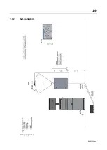
Page 19: ...19 BA023001 en 2 3 2 Set up diagram Set up diagram I ...
Page 20: ...20 BA023001 en Set up diagram II ...
Page 22: ...22 BA023001 en 2 4 1 Wiring diagram ...
Page 23: ...23 BA023001 en 2 4 2 Control cabinet structure Basic variant ...
Page 24: ...24 BA023001 en 2 4 3 Control cabinet structure Full equipment ...
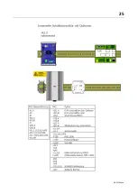
Page 25: ...25 BA023001 en ...
Page 53: ...53 BA023001 en ...
Page 138: ...138 BA023001 en 13 Annex 13 1 Naming convention ...


