


49
BA023001-en
6
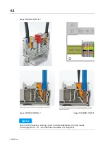
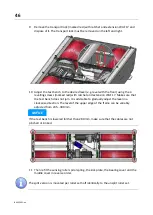
Secure the cable in the reel set using cable ties. Make sure that no cables are
under tensile stress.
7
On the control cabinet side, shorten the supplied flexible plastic protective conduit
with an inner diameter of 36 mm to the required length, push it over the cables
protruding from the empty conduit and allow it to protrude several centimetres
into the empty conduit in the floor.
Insert the cables on the underside of the control cabinet at -UB2 (PG36) of the
cable entry. Push the plastic protective hose into the cable entry until it locks into
place.
8
Inside the control cabinet, relieve the strain on all cables at the existing cable tie
(above the cable entry).
9
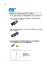
Shorten the two motor cables to the required length, strip them and connect the
individual wires to the push-in spring-loaded terminals (motor terminals) -X1L
without tensile load. To do this, strip and twist the individual wires 10...12 mm.
Make sure that the spring-loaded terminal does not squeeze on the insulation of
the single wire.
Image: PHOENIX CONTACT
Summary of Contents for CONNECT Series
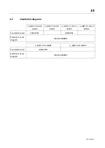
Page 19: ...19 BA023001 en 2 3 2 Set up diagram Set up diagram I ...
Page 20: ...20 BA023001 en Set up diagram II ...
Page 22: ...22 BA023001 en 2 4 1 Wiring diagram ...
Page 23: ...23 BA023001 en 2 4 2 Control cabinet structure Basic variant ...
Page 24: ...24 BA023001 en 2 4 3 Control cabinet structure Full equipment ...
Page 25: ...25 BA023001 en ...
Page 53: ...53 BA023001 en ...
Page 138: ...138 BA023001 en 13 Annex 13 1 Naming convention ...