40
BA023001-en
4.3
Mounting the control cabinet
4.3.1
Mechanical installation
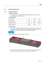
Installation accessories
•
3 pcs hexagonal wood screws 6x60 mm, MAHA # 22 0571060 1.
•
3 pcs 6 mm washers, MAHA # 22 0125 06 3.
•
3 pcs 8 mm anchors, MAHA # 23 5008. These anchors are suitable for normal con-
crete, masonry walls, light weight concrete with a high degree of porosity and aer-
ated concrete. For other materials, suitable fastening systems must be used on
site!
Installation process
1
Mark the drill holes on the selected wall according to the sketch and with the aid
of a spirit level and drill to a depth of at least 60 mm using a suitable 8 mm
masonry drill bit.
2
Insert the anchors and screws into the holes and screw them in at a distance of
10 mm from the wall.
3
Hang the control cabinet on the pre-installed screws using the keyholes, align with
a spirit level if necessary and tighten the screws.
NOTICE
Check control cabinet for tight fit after installation.
Summary of Contents for CONNECT Series
Page 19: ...19 BA023001 en 2 3 2 Set up diagram Set up diagram I ...
Page 20: ...20 BA023001 en Set up diagram II ...
Page 22: ...22 BA023001 en 2 4 1 Wiring diagram ...
Page 23: ...23 BA023001 en 2 4 2 Control cabinet structure Basic variant ...
Page 24: ...24 BA023001 en 2 4 3 Control cabinet structure Full equipment ...
Page 25: ...25 BA023001 en ...
Page 53: ...53 BA023001 en ...
Page 138: ...138 BA023001 en 13 Annex 13 1 Naming convention ...

