background image

62


BA023001-en 


Select TP_LINK_xxxx. 


Enter password. 

If no WiFi device is found, the connection must be set up manually using the SSID and 
the PIN. 


Alternatively, free QR code generators can be found on the Internet, which can be 
used to generate a personal QR code for the CONNECT brake tester. 


If this is photographed (e.g. on iOS devices) or scanned with a QR code 
scanner app, the standard browser is automatically opened and the Inter-
net address entered. 


6.3.5


Variant 3: Integration of the test bench into own network 

Alternatively, the ZM of the test bench can also be integrated into a company network. 
For this purpose, the Ethernet port X12 "EXT" can be configured analogue to a LAN 
interface of a PC:  


DHCP client:  
The Ethernet port X12 "EXT" of the ZM can be configured as a DHCP client so that 
it is assigned an IP address by the local DHCP server. 


Static IP address:  
The Ethernet port X12 "EXT" can be assigned a fixed IP address and a default 
gateway. 

This means that the brake tester can be reached within the network by connecting a 
computer via network cable to a usual network socket of this network. If this network 
also offers WiFi access, it is possible for the test bench to be operated directly via WiFi-
capable terminals: 


Turn on computer/mobile device, log in after booting, open browser. 


Establish the browser connection as described above. 


6.4


Test procedure 

6.4.1


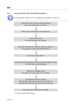
Drive on test bench 


NOTICE


Drive slowly (walking speed), centrally and straight on the test bench. The left and 
right sensing rollers must be actuated simultaneously. 


Summary of Contents for CONNECT Series

Page 1: ...r Passenger Cars and Vans Original Operating Instructions BA023001 en C_MBT C 3 5 W220 C_MBT S 3 5 W220 C_MBT C 3 5 W250 C_MBT S 3 5 W250 C_MBT C 4 0 W220 C_MBT S 4 0 W220 C_MBT C 4 0 W250 C_MBT S 4 0 W250 C_MBT C 5 0 W280 C_MBT S 5 0 W280 ...

Page 2: ...the event of the grant of a patent utility model or design The contents of this edition have been checked with great care However errors cannot be fully excluded Subject to technical change without notice Manufacturer MAHA Maschinenbau Haldenwang GmbH Co KG Hoyen 20 87490 Haldenwang Germany Phone 49 8374 585 0 Fax 49 8374 585 590 Mail maha maha de Web www maha de Service MAHA SERVICE CENTER Maybac...

Page 3: ... test of vehicles with one driven axle 11 2 2 5 Brake test of four wheel drive vehicles 12 2 2 6 Overview with components 14 2 3 Technical data 15 2 3 1 Safety area 18 2 3 2 Set up diagram 19 2 4 Control unit description 21 2 4 1 Wiring diagram 22 2 4 2 Control cabinet structure Basic variant 23 2 4 3 Control cabinet structure Full equipment 24 2 4 4 Connection and termination of the central modul...

Page 4: ... bench 60 6 3 2 Variant 1 Establish LAN connection to PC notebook 60 6 3 3 Establish a browser connection 60 6 3 4 Variant 2 Establishing a WiFi connection 61 6 3 5 Variant 3 Integration of the test bench into own network 62 6 4 Test procedure 62 6 4 1 Drive on test bench 62 6 4 2 Carry out brake test with automatic sequence 63 6 4 3 Carry out brake test with semi automatic sequence 64 6 4 4 Carry...

Page 5: ...usting the brake force 87 6 8 4 Test bench settings 87 6 8 5 Options overview 88 6 8 6 Software update 88 6 8 7 Input output test 89 6 9 Deceleration table 90 7 Inspection and maintenance 91 7 1 Safety instructions 91 7 2 Care instructions 92 7 3 Inspection and maintenance schedule 92 7 4 Maintenance of the chains 92 7 4 1 Cleaning the chains 93 7 4 2 Checking for chain wear 93 7 4 3 Retensioning ...

Page 6: ...Description 113 11 3 2 Scope of delivery 114 11 3 3 Technical data 114 11 3 4 Installation 114 11 3 5 Status LEDs 117 11 3 6 Setup 118 11 3 7 Function test 122 11 3 8 Update 123 11 3 9 Other 123 11 4 C_BOX 124 11 4 1 Description 124 11 4 2 Scope of delivery 125 11 4 3 Display requirements 125 11 4 4 Installation 125 11 4 5 Connecting the C_BOX with the brake tester 126 11 4 6 Coupling with the bra...

Page 7: ...elevant regulations regarding accident prevention and health and safety must be observed 1 2 Symbols and signal words 1 2 1 Personal injury DANGER indicates an imminent danger Death or severe injuries will follow if this danger is not avoided WARNING indicates a potentially imminent danger Death or severe injuries may follow if this danger is not avoided CAUTION indicates a potentially imminent da...

Page 8: ...urred o Who is reporting the accident Keep calm and answer questions 1 5 Requirements for operators and service personnel Only persons qualified for testing in accordance with TRBS 1203 may be used as service personnel All persons involved in the operation maintenance assembly dismantling and disposal of the equipment must be 18 years of age or older have the mental and physical capacity for their...

Page 9: ... by the manufacturer or persons authorized by them Among other things the safety structures are to be inspected and if necessary other parts are to be replaced in accordance with the manufacturer s specifications 2 2 General machine description 2 2 1 Structure and legend Structure of the test bench 1 Immediate danger zone around the test bench within the inner yel low black markings 2 Area of the ...

Page 10: ...red for safe operation In the simplest case the display unit is a monitor of an existing PC or a notebook in the immediate vicinity of the test bench and is connected to the control unit via LAN cable or wirelessly via WiFi Furthermore a commercially available TV monitor together with a MAHA C_BOX or the MAHA universal analogue display can be used as a simultaneous display If WiFi is available a b...

Page 11: ... the test bench can also be set up outdoors Prior consultation necessary 2 2 4 Brake test of vehicles with one driven axle The vehicle is driven into the roller set with the axle to be tested At the same time the two sensing rollers that measure the wheel speed are pressed down A warning message is issued and after approx 3 seconds the two drive motors of the roller set are started so that both ve...

Page 12: ...rupt frictional connection will put mechanical stress on the differential Vehicles in which the four wheel drive system has been deactivated by removing fuses behave like a conventional two wheel drive i e the test bench can be left with the rollers rotating The fuse shall not be reinserted until the brake performance test has been completed and the vehicle has finally exited the test bench Mode 2...

Page 13: ...omatically reversed The braking force of the respective wheel turning forwards is measured After completion of the two measurements the test bench rollers remain stationary until the vehicle has exited the test bench NOTICE In the case of automatic four wheel drive detection the vehicle engine must NOT be switched off after driving on the test bench otherwise correct four wheel drive detection is ...

Page 14: ...rview with components 1 Test bench rollers 2 Electric motor 3 Sensing roller with slip and drive sensor Namur 4 Middle cover shown transparently 5 Bearing cover shown transparent 6 IFM Interface module Overview with components ...

Page 15: ...ded textured surface friction coefficient dry wet 0 9 0 7 0 9 0 7 0 9 0 7 0 9 0 7 Test roller with plastic granulate coating friction value dry wet 0 9 0 8 0 9 0 8 0 9 0 8 0 9 0 8 MIXED roller friction coef ficient dry wet 0 9 0 8 0 9 0 8 0 9 0 8 0 9 0 8 Measuring range 0 8 kN 0 8 kN 0 8 kN 0 8 kN Measuring range MIXED roller 0 6 kN 0 6 kN 0 6 kN 0 6 kN Display accuracy full scale 2 2 2 2 Fuse 25 ...

Page 16: ...red surface friction coefficient dry wet 0 9 0 7 0 9 0 7 0 9 0 7 0 9 0 7 Test roller with plastic granulate coating friction value dry wet 0 9 0 8 0 9 0 8 0 9 0 8 0 9 0 8 MIXED roller friction coef ficient dry wet 0 9 0 8 0 9 0 8 0 9 0 8 0 9 0 8 Measuring range 0 8 kN 0 8 kN 0 8 kN 0 8 kN Measuring range MIXED roller 0 6 kN 0 6 kN 0 6 kN 0 6 kN Display accuracy full scale 2 2 2 2 Fuse 25 A gG 25 A...

Page 17: ...0 7 Test roller with plastic granulate coating friction value dry wet 0 9 0 8 0 9 0 8 MIXED roller friction coef ficient dry wet 0 9 0 8 0 9 0 8 Measuring range 0 8 kN 0 8 kN Measuring range MIXED roller 0 6 kN 0 6 kN Display accuracy full scale 2 2 Fuse 25 A gG 25 A gG Power supply 3x 400 V N PE 50 Hz 3x 400 V N PE 50 Hz Minimum cable cross section Supply line 5 x 4 0 mm 5 x 4 0 mm Dimensions H x...

Page 18: ...en 2 3 1 Safety area When operating the test bench there must be no persons or obstacles danger of crushing in the safety area This shall be indicated by a yellow and black marking around the test bench Safety area ...

Page 19: ...19 BA023001 en 2 3 2 Set up diagram Set up diagram I ...

Page 20: ...20 BA023001 en Set up diagram II ...

Page 21: ...al further contactors for additional functions such as multi function con trol star delta start up 2 test speeds etc Switching power supply 24 V DC supply of the control boards and contactors fuse protection via circuit breaker Optional soft start module SA to reduce the inrush current peak supports the automatic four wheel drive detection option automatic meas urement in counter rotation Optional...

Page 22: ...22 BA023001 en 2 4 1 Wiring diagram ...

Page 23: ...23 BA023001 en 2 4 2 Control cabinet structure Basic variant ...

Page 24: ...24 BA023001 en 2 4 3 Control cabinet structure Full equipment ...

Page 25: ...25 BA023001 en ...

Page 26: ...26 BA023001 en 2 4 4 Connection and termination of the central module ZM Connection of the central module ...

Page 27: ...27 BA023001 en 2 4 5 Coding ZM OM Connection of the option modules ZM OM Possibility 1 ZM only Central module ZM S2 S A1 0 S2 Term ON ...

Page 28: ...2 S A1 0 S2 Open Term OFF Option module OM S option S1 S2 S3 Open Term OFF A2 0 Direction of rota tion measurement via pushbutton 0 0 15 Term ON only at the last mod ule A2 1 Lowering bar 1 0 15 A2 2 Roller set lift 2 0 15 A2 3 Number plate recognition 3 0 15 ...

Page 29: ...001 en 2 4 6 Coding ZM IFM Connection of the interface module ZM IFM CAN address IFM CT S1 Termination OFF Terminating resistor OFF S1 Termination ON Terminating resistor ON 0 0 8 IFM BA 1 1 9 2 2 A 3 3 B 4 4 C ...

Page 30: ...inating resistor OFF S1 Termination ON Terminating resistor ON 5 5 D 6 6 E 7 7 F IFM BA always preset with address 0 and term ON Possibility 1 Closed roller set Central module ZM S3 S A1 0 S3 Term ON Interface module Basic IFM BA no rotary switch S1 available ...

Page 31: ...31 BA023001 en Possibility 2 Closed roller set Central module ZM S3 S A1 0 S3 Term ON Interface module Comfort IFM CT S3 A A3 S1 Term ON Address 0 rotary switch S1 to 8 ...

Page 32: ...t roller set Central module ZM S3 S A1 0 S3 Open Term OFF Left interface module Comfort IFM CT S1 A A3 S1 Term ON Address 1 rotary switch S1 to 9 Right interface module Comfort IFM CT S1 B A3 S1 Term ON Address 2 rotary switch S1 to A ...

Page 33: ... set in series ZM IFM IFM Central module ZM S3 S A1 0 S3 Term ON Left interface module Comfort IFM CT S1 A A3 S1 Term OFF Address 1 rotary switch S1 to 1 Right interface module Comfort IFM CT S1 B A3 S1 Term ON Address 2 rotary switch S1 to A ...

Page 34: ... On indicator light P1 in the front cover of the control cabinet lights up as soon as the main switch is switched on and the control is initialised and there is no fault In the event of a fault the mains lamp flashes at a frequency of 1 Hz For detailed error code list see section Trouble shooting and error resolution ...

Page 35: ...or must provide optional safeguards e g warning lamps barriers mon itoring of the presence of personnel in working pits in accordance with the on site conditions Personal protective equipment safety boots and gloves must be worn The per sonal protective equipment must meet the safety requirements for the particular work being performed Secure the roller set with suitable means e g barrier chain or...

Page 36: ... C_MBT C 3 5 W250 Unsplit roller set 3 5 t Control cabinet Operating instructions circuit diagram Packaging C_MBT S 3 5 W250 Split roller set 3 5 t Control cabinet Operating instructions circuit diagram Packaging C_MBT C 4 0 W220 Unsplit roller set 4 0 t Control cabinet Operating instructions circuit diagram Packaging C_MBT S 4 0 W220 Split roller set 4 0 t Control cabinet Operating instructions c...

Page 37: ...d handling of the test bench is only permitted in the original packaging On the pallet the packed test bench can be moved with the forklift truck For loading unloading and insertion into the foundation use the pick up points shown below Hand over the load suspension lugs to the operator for reuse dismantling repair after the transport process Dimensions and centre of gravity of the packed test ben...

Page 38: ...t and recorded All parts of the electrical equipment must be protected from moisture and humidi ty Even when the main switch is switched off parts of the optional control cabinet heater components terminals cores cables etc are still live During service work the system must be depressurised and de energised For all work including assembly repair and maintenance work on the test bench e g control c...

Page 39: ...3 5 4 0 W220 C_MBT S 3 5 4 0 W220 C_MBT C 3 5 4 0 W250 C_MBT S 3 5 4 0 W250 Foundation plan 10022761 10022761 Electrical circuit diagram 202 01 005800 C_MBT C 5 0 W280 C_MBT S 5 0 W280 Foundation plan 10022761 Electrical circuit diagram 202 01 005800 ...

Page 40: ... other materials suitable fastening systems must be used on site Installation process 1 Mark the drill holes on the selected wall according to the sketch and with the aid of a spirit level and drill to a depth of at least 60 mm using a suitable 8 mm masonry drill bit 2 Insert the anchors and screws into the holes and screw them in at a distance of 10 mm from the wall 3 Hang the control cabinet on ...

Page 41: ...the control cabinet and tighten the cable gland using an open end wrench Tension check on the cable whether the cable gland closes correctly 2 Fix the supply line to the wall so that there is no tensile load on the screw connection 3 Connect the single wires of the stripped supply cable to the push in supply cable terminals X1L without tensile load To do this strip the insulation from the individu...

Page 42: ... en Image PHOENIX CONTACT Image PHOENIX CONTACT Image PHOENIX CONTACT NOTICE Ensure that the yellow warning covers are then reattached to the terminals The supply line L1 L2 L3 must have a clockwise rotating field ...

Page 43: ...t Nm 35 Nm Width across flats WAF mm 17 Assembly process 1 Lift the roller set into the prefabricated foundation using a suitable four part chain hanger on the 4 lugs on the middle cover If the wiring harness is pre installed it must be inserted into the empty conduit provided at the same time NOTICE Make sure that the cables are not pinched or kinked 2 After lowering into the foundation the suspe...

Page 44: ...for reuse disassembly repair 4 Remove the bearing covers on the left and right so that the test bench can be fixed in the foundation To do this remove the 4 M8 screws marked red with WAF 13 and remove the bearing covers 5 Dismantle the kick plates To do this remove the4 M10 screws marked red with WAF 17 ...

Page 45: ...tically on the left and right 7 Center the test bench all around in the foundation then drill a minimum depth of 90 mm at the fixing points marked red using a suitable 10 mm masonry drill bit The fixing holes must be made identically on the left and right 8 Drive in the bolt anchor check the test bench centering in the foundation again Tighten bolt anchor with ratchet and extension WAF 17 ...

Page 46: ... Make sure that the test bench does not jam It is advisable to gradually adjust the level in a clockwise direction The level of the upper edge of the frame can be variably adjusted from 245 300 mm NOTICE If the test bench is lowered further than 280 mm make sure that the cables are not pinched or kinked 11 Then refit the sensing roller spiral spring the kick plate the bearing cover and the middle ...

Page 47: ...able left track A and right track B MAHA 1404769 Cable 7G 1 5 mm YSLY JZ 15 meters Round plug 7 pin b CAN data line IFM MAHA 1402469 Cable 2x2x0 5 mm PVC data cable 15 meters Connector M12 4 pin Pinout Pin 1 YE Pin 2 GN Pin 3 WH Pin 4 BN c Protective earth conductor MAHA 1402470 Single core GN YE 4 0 mm PVC flexible 15 meters Cable lug Ø 6 5 mm ...

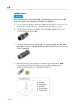
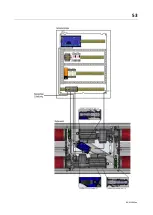
Page 48: ...ection of the control box 2 Connect the two motor cables directly to the couplings provided on the motor until the plug connection engages 3 Pull off the protective cap from X1 on the IFM Carefully plug the CAN data cable with the M12 connector onto the and tighten the locking ring on the connector by turning it clockwise 4 Attach the cable lug of the protective conductor single wire by means of M...

Page 49: ...s on the underside of the control cabinet at UB2 PG36 of the cable entry Push the plastic protective hose into the cable entry until it locks into place 8 Inside the control cabinet relieve the strain on all cables at the existing cable tie above the cable entry 9 Shorten the two motor cables to the required length strip them and connect the individual wires to the push in spring loaded terminals ...

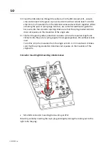
Page 50: ...aded terminal does not squeeze on the insulation of the single wire 11 Shorten the green yellow protective conductor wire to the required length and clamp it onto the push in spring cage terminal green yellow X1L without tensile load To do this strip the insulation from the single wire 10 12 mm and twist it Make sure that the spring loaded terminal does not squeeze on the insulation of the single ...

Page 51: ...he 3 4 pin connector It is locked by lightly snapping into place when plugged in The connector must not be turned under pressure M8 protective cap mounting dismounting on IFM Unused plug in connections must be fitted with a black rubber protective cap If necessary remove these by pulling gently ...

Page 52: ...t by carefully plugging in the 7 pin connector It is locked by lightly snapping into place when plugged in The connector must not be turned For dismounting use a screwdriver to lightly press the locking lug and pull off the connector while doing so 1 2 1 2 3 ...

Page 53: ...53 BA023001 en ...

Page 54: ...ull and returned to the manufacturer During the acceptance process the following points must be checked again in particular Free movement of sensing roller holder and sensing roller Electrical connection of the brake tester Potential equalisation Correct setting of all Namur sensors check via Service technician menu Firm fit of control cabinet and brake tester Smooth running of the motors WARNING ...

Page 55: ...cover and mount the adjustment device 2 Measure the roller diameter 3 Fit the adjustment device to the left hand motor of the roller set in the direction of travel 4 Attach the counterweight and level the adjustment device Use the counterweight to bring about balance Only when the adjustment device is in equilibrium does no force act on the range spring The counterweight on the left side balances ...

Page 56: ...act alignment 7 Preload the adjustment device 3x with maximum value 8 Perform adjustment press Adjust button 9 Remove the weight and check the zero point The zero point must not be re adjusted again It must therefore be ensured that no force acts on the brake tester s range spring when no weight is applied If there are excessive deviations the adjustment must be performed again 10 Repeat the proce...

Page 57: ...e lighting of the work area must be provided When the system is not being used it must be switched off and the main switch must be secured with a padlock to prevent it from being switched back on In emergency situations switch off the system with the emergency stop main switch or emergency stop pushbutton No persons may be present in the danger zone of the system during driving and vehicle testing...

Page 58: ...ndependent start up of the test rollers is also possible without an active display e g TV set monitor smart device Start up monitoring The start up monitoring prevents the rollers from starting up if the wheels are locked up bearing jammed brake pads stuck This device protects the vehicle the vehicle s tyres from damage Sensing rollers The magnitude of the slip is determined from the comparison of...

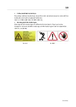
Page 59: ... cordon off the test bench and must be replaced if defective Item no 19 6014 38 mm 19 6015 50 mm Warning and information signs Warning and information signs are affixed to the test bench They must not be changed or removed Defective warning and information signs must be replaced for item no see below 54 2132 54 2683 ...

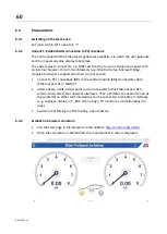
Page 60: ...ed in their current version Connect a PC or notebook NB to the central module ZM via network cable Ethernet port X13 MAHA Alternatively a WiFi access point can be connected to this Ethernet port X13 which usually offers four network interfaces Then a PC NB is connected to one of these interfaces Other terminal devices can be connected to the other interfaces e g analogue display or C_BOX when usin...

Page 61: ...makes it possible to use browser capable smart devices SmartPhone tablet PC in addition to the PC NB to operate the brake tester and display the measured values Windows PC On the underside of the router there is a label that indicates the name next to SSID and the wireless password next to PIN Connect WiFi router TP Link with power supply and switch on In the Network and Sharing Center select WiFi...

Page 62: ...alogue to a LAN interface of a PC DHCP client The Ethernet port X12 EXT of the ZM can be configured as a DHCP client so that it is assigned an IP address by the local DHCP server Static IP address The Ethernet port X12 EXT can be assigned a fixed IP address and a default gateway This means that the brake tester can be reached within the network by connecting a computer via network cable to a usual...

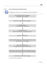
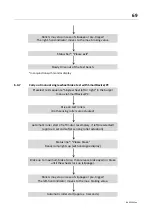
Page 63: ...actuated Automatic roller start approx 3 seconds after sensing roller actuation Status line Please brake Brake up to maximum brake force then release brake again or brake until the wheels lock up slippage Rollers stop if slippage occurs The indicators move to the max brake values Exit while test rollers are running directly while rollers are still run ning or when they start up again approx 3 seco...

Page 64: ...emi automatic roller start after sensing roller actuation and release by remote control smart device Status line Please brake Brake up to maximum brake force then release brake again or brake until the wheels lock up slippage Rollers stop if slippage occurs The indicators move to the max brake values Exit while test rollers are running directly while rollers are still running or when they are rest...

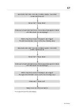
Page 65: ...tion In the event of increased starting resistance due to the four wheel drive the motors switch off again immediately Start up monitoring Automatic roller start approx 3 seconds In the event of increased starting resistance due to the four wheel drive the motors switch off again immediately Four wheel drive detected Automatic roller start in counter rotation approx 3 seconds motor left forward St...

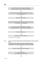
Page 66: ...ppage Rollers may stop in case of slippage or pre trigger The right hand indicator moves to the max braking value Status bar Please exit Slowly drive out of the test bench In conjunction with monitor display 6 4 5 Carry out manual four wheel brake test with SmartDevice PC in counter rotation mode Preselect the Four wheel test sequence in the burger menu via SmartDevice PC four wheel drive and auto...

Page 67: ...igger The left hand indicator moves to the max braking value Automatic roller start in counter rotation approx 3 seconds motor right forward Status line Please brake Brake up to maximum brake force then release brake again or brake until the wheels lock up slippage Rollers may stop in case of slippage or pre trigger The right hand indicator moves to the max braking value Status bar Please exit Slo...

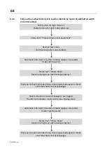
Page 68: ...econds motor left forward Status line Please brake Ready lamp lights up with analogue display Brake up to maximum brake force then release brake again or brake until the wheels lock up slippage Rollers may stop in case of slippage or pre trigger The left hand indicator moves to the max braking value Automatic roller start in counter rotation approx 3 seconds motor right forward Status line Please ...

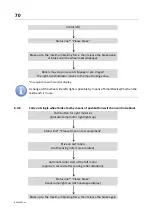
Page 69: ... right in the burger menu via SmartDevice PC Drive on test rollers both sensing rollers are actuated Automatic roller start of left motor exemplary if left preselected approx 3 seconds after sensing roller actuation Status line Please brake Ready lamp lights up with analogue display Brake up to maximum brake force then release brake again or brake until the wheels lock up slippage Rollers may stop...

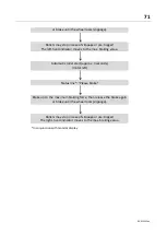
Page 70: ...possible by means of SmartDevice PC when the test bench is in use 6 4 8 Carry out single wheel brake test by means of pushbutton switch on control cabinet Push button for right motor 2x indicator lamp motor right lights up Status line Please drive on test equipment Drive on test rollers both sensing rollers are actuated Automatic roller start of the left motor approx 3 seconds after sensing roller...

Page 71: ... max braking value Automatic roller start approx 3 seconds motor left Status line Please brake Brake up to the maximum braking force then release the brake again or brake until the wheel locks slippage Rollers may stop in case of slippage or pre trigger The right hand indicator moves to the max braking value In conjunction with monitor display ...

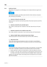
Page 72: ... bench d Static exit aid DC brake or electromechanical motor brake Vehicle may be driven out of the test bench even with the rollers stationary e Emergency exit aid If the rollers are passively accelerated by a vehicle the motors are automatically switched on from a speed of 5 km h The vehicle can be driven out of the test bench NOTICE In case of malfunction or failure of the motor brake or the au...

Page 73: ...witch between the results screen and the measurement screen for touch enabled devices this can also be done by swiping to the side A Hamburger menu Opens a list of functions and procedures B Settings Click on cogwheel opens menu with settings C Delete Discards the current measurement results D Measurement results Displays the brake force left right difference and de celeration if pTW is known for ...

Page 74: ...mileage of the vehicle in km L pTW Entering the permissible total weight in kg 6 6 Measured value display Once the test rollers have been driven on to the display automatically changes to the measurement screen In the measurement screen the current brake values and the difference in are shown After slip or pre trigger memory threshold the maximum braking forces of the measurement are displayed A H...

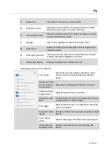
Page 75: ... I Differential display Displays the brake force differential in Hamburger menu list of functions Four wheel Automatic counter rotation operation meas urement of the respective forward rotating wheel Reversal of direc tion of rotation measurement Measures in the opposite direction of travel Individual wheel measurement Measurement of only one wheel Automatic roller start If deactivated the rollers...

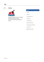
Page 76: ...76 BA023001 en 6 7 Settings Clicking on the gear symbol in the MAHA logo opens the settings menu This menu contains the following sub menus ...

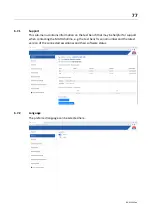
Page 77: ...ation on the test bench that may be helpful for support when contacting the MAHA hotline e g the test bench s serial number and the latest version of the connected assemblies and their software status 6 7 2 Language The preferred language can be selected here ...

Page 78: ...mer network see section Operation Preparations Variant 3 Integration of the test bench into own network To change the configuration of one of these interfaces it is necessary to log in to the Service technician menu The Ethernet interface X13 is permanently configured on the central module MAHA and cannot be changed 6 7 4 Event logging A history of all stored error messages codes and events change...

Page 79: ...79 BA023001 en 6 7 5 Test report Here the content of the test report can be determined depending on the installed options ...

Page 80: ...vailable here including a fault memory and detailed machine data 6 7 7 Calibrating brake force This sub menu displays the calibration values for the brake forces If the test bench needs to be adjusted login is required in the Service technician menu see section Service technician menu login ...

Page 81: ...oller and sensing roller This view is used to diagnose problems such as defective sensor cable interruption etc Once the user has logged in as service technician the motors can also be started from this menu An additional deadman s control is necessary for this however This control must be connected in the control cabinet ...

Page 82: ...tion test can also be carried out 6 7 10 Service technician menu login The Service technician menu can be opened However this menu is only accessible to persons who are registered with MAHA and have an access account or a software key maha key These keys are limited in time usually one week after issuance and are only valid for a specific test bench ...

Page 83: ...lly administered by the MAHA Service Center after MAHA training has been completed Offline activation If the test bench is not online the user can log in by means of a software key maha key This file must be downloaded to the end device beforehand and can be imported into the test bench here using the Browse button 6 8 Service technician menu After login the menu expands or changes ...

Page 84: ... out 6 8 2 Network The central module has two Ethernet interfaces X13 MAHA and X12 EXT The current configuration of these interfaces can be seen in the network area of the Service technician menu The designation of the X12 EXT interface is Customer network that of the X13 MAHA interface MAHA network ...

Page 85: ...the address 192 168 202 1 If this setting is made it must be ensured that the network in which the central mod ule or its X12 EXT is operated does not have another DHCP server Multiple DHCP serv ers on a network cause network problems DHCP client To configure the X12 EXT interface as a DHCP client Client must be selected as the new mode After a restart of the central module the X12 EXT interface t...

Page 86: ...would be e g http maha mbt maha 3 Login in the Service technician menu e g via a previously downloaded offline key 4 Switch to the network area select the desired mode and enter the desired configuration Incorrect configuration of the X12 EXT interface can result in the central module no longer being accessible via the X12 EXT interface A configuration correction can or must then be made via the X...

Page 87: ...01 1 and distributes IP addresses in the network in which the X13 MAHA interface is located This configuration cannot be changed On the one hand this ensures that the MAHA Access Point functions correctly with this interface and on the other hand it allows the network configuration of the X12 EXT interface to be performed via the X13 MAHA port 6 8 3 Adjusting the brake force See section Calibratio...

Page 88: ... test bench options is shown here If the slide switch is moved to the right the option is highlighted in blue is now active and can be used provided that no mechanical changes add ons are necessary for this 6 8 6 Software update Software updates can be performed here ...

Page 89: ...89 BA023001 en 6 8 7 Input output test A test of the inputs and outputs of the central module can be performed here ...

Page 90: ... 700 14 29 43 57 71 86 100 800 13 25 38 50 63 75 88 100 900 11 22 33 44 56 67 78 89 100 1000 10 20 30 40 50 60 70 80 90 100 1100 9 18 27 36 45 55 64 73 82 91 100 1200 8 17 25 33 42 50 58 67 75 83 92 100 1300 8 15 23 31 38 46 54 62 69 77 85 92 100 1400 7 14 21 29 36 43 50 57 64 71 79 86 93 100 1500 7 13 20 27 33 40 47 53 60 67 73 80 87 93 100 1600 6 13 19 25 31 38 44 50 56 63 69 75 81 88 94 100 Dec...

Page 91: ...ried out and recorded All parts of the electrical equipment must be protected from moisture and humidi ty Even when the main switch is switched off parts of the optional control cabinet heater components terminals cores cables etc are still live During service work the system must be depressurised and de energised For all work including assembly repair and maintenance work on the test bench e g co...

Page 92: ...st bench for damage Monthly Clean retighten and lubricate chains Lubricate sensing roller hinges Annually The maintenance interval prescribed by the manufacturer is 12 twelve months This maintenance interval refers to normal workshop use If the device system is used more frequently or under more difficult operating conditions e g in outdoor areas the interval must be shortened accordingly Maintena...

Page 93: ...is suitable for all chains of the MAHA test benches It can be used for type 12B 3 4 and type 16B 1 chains If the chain wear gauge dips completely as can be seen below it is imperative that the chain is replaced as otherwise consequential damage can occur e g to the sprockets Chain pitch CONNECT SERIES MBT SERIES 12B 3 4 C_MBT C S 1 0 Wxxx MBT 1000 C_MBT C S 3 5 4 0 5 0 Wxxx MBT 2000 C_MBT C 8 0 W2...

Page 94: ...g screws of the pedestal bearings on both sides 2 Adjust the chain to the correct tension using the adjusting screw 3 Move the roller s in parallel not one sided 4 Retighten the fastening screws tightening torques see table NOTICE It is recommended by the manufacturer that the fastening screws be replaced each time an adjustment is made 5 Use a medium strength threadlocker 6 Recheck chain tension ...

Page 95: ...ng torque Position Required for chain tension C_MBT 3 5 4 0 5 0 M10 8 8 50 Nm Roller Yes M16 8 8 120 Nm Motor bearing No Test bench type Thread Strength Tightening torque Position C_MBT 3 5 4 0 5 0 M8 12 9 40 Nm Range spring M10 12 9 85 Nm Range spring Tightening torques of the set screws M6x0 75 WAF 3 6 Nm M10x1 25 WAF 5 26 Nm M8x1 WAF 4 14 Nm M12x1 5 WAF 6 42 Nm ...

Page 96: ...ength while continuing to turn the rollers by hand Important The lubricant must get into the chain joint Inadequate lubrication can be recognised on the basis of the following signs Increased noise Stiff joints Increased power consumption Fretting corrosion in the chain links In the case of inadequate lubrication proceed as follows Clean the chain with a very low viscosity oil This will flush fret...

Page 97: ...erval 200 operating hours 12 months 1 Remove cover plate from roller set 2 Treat lubrication points arrow with sprayable lubricant While doing this move the sensing roller up and down Carry out the procedure on both sensing rollers 3 Re mount the cover plate on the roller set ...

Page 98: ...e carried out and recorded All parts of the electrical equipment must be protected from moisture and humidi ty Even when the main switch is switched off parts of the optional control cabinet heater components terminals cores cables etc are still live During service work the system must be depressurised and de energised For all work including assembly repair and maintenance work on the test bench e...

Page 99: ...ror code group is indicated by the two pointers the complete 5 digit error code must be taken from the log file Error code 01000 Description Incomplete adjustment of the braking force Possible solution Carry out the adjustment of the braking force Error code 02000 Description Incomplete adjustment of the weighing device Possible solution Carry out the adjustment of the weighing device Error code 1...

Page 100: ...iption CAN bus error Possible solution Connect CAN bus cable if required Restart of entire system Error code 12001 Description Error when querying the calibration values in the EEPROM Possible solution Connect CAN bus cable if required Restart the entire system Error code 12002 Description Error when configuring the measuring amplifier of the left range spring Possible solution Connect CAN bus cab...

Page 101: ...n Switch off the entire system Check the wiring of the speed sensor on the interface module Error code 32002 Description Missing pulses at the speed sensor of the left sensing roller Possible solution Error code 34000 Description Short circuit at the speed sensor of the right sensing roller Possible solution Switch off the entire system Check the wiring of the speed sensor on the interface module ...

Page 102: ... system Check the wiring of the speed sensor on the interface module Error code 37001 Description Cable break at the speed sensor of the right test roller Possible solution Switch off the entire system Check the wiring of the speed sensor on the interface module Error code 37002 Description Missing pulses at the speed sensor of the right test roller Possible solution Error code 40000 Description Z...

Page 103: ...Namur sensor Occupied right Possible solution Switch off the entire system Check the wiring of the Namur sensor on the interface module Error code 42002 Description One side occupied detected on the right Possible solution Drive on test bench on both sides if this error is not yet displayed only info via status line Drive vehicle off the test bench Error code 51000 Description Test bench occupied ...

Page 104: ...escription Occupied at Namur sensor Drive on side Possible solution Vehicle is on the test plate drive off restart the entire system Readjustment of the system Error code 72000 Description Short circuit at Namur sensor Drive off side Possible solution Switch off the entire system Check the wiring of the Namur sensor on the interface module Error code 72001 Description Cable break at Namur sensor D...

Page 105: ...Software key installer key token Software image NOTICE The technician key must not be older than the software image It is recommended to always download key and software at the same time Both can be downloaded from https www maha de de software CONNECT DOWNLOADS The following steps must be observed when replacing the control unit 1 Replace the central module with the main switch switched off 2 Res...

Page 106: ...ntral module has never been installed a reset is not necessary and also not possible Start screen of a new or reset board Service technician login is possible only with offline activation 4 Perform a software update see section Operation Service technician menu Software update Only a manual update can be performed since no network setting is available yet 5 After the software update has been compl...

Page 107: ...leased see section Repair Releasing the motors with mechanical brake Check range spring signal Load the brake roller or motor in one direction and check whether the measured values on the test bench display change This is only a function check Check weighing sensors Load the test bench at each corner and observe a change in the measured value via the service technician screen This is only a functi...

Page 108: ... applied brake When the voltage is switched off the motor is blocked A special motor connection cable can be used to release the brake and allow the motor to be rotated by hand for service purposes Installation only in the switched off state taking into account the 5 safety rules Motor connection with mechanical brake ...

Page 109: ... motor supply cable plug from the motor in the roller set 2 Connect the motor plug of the brake release adapter to the motor 3 Connect the shockproof plug from the brake release adapter to 230 VAC 50 60 Hz L N PE shockproof socket max B16A 30 mA RCD 4 Test roller can be rotated by hand 5 Remove the brake release adapter after use ...

Page 110: ...r in the roller set 2 Connect the motor plug from the brake release adapter jack to the motor 3 Connect the motor supply cable plug to the brake release adapter pins Intermediate piece in motor supply line 4 Select and enable the required test roller side via the Service technician menu 5 Test roller can be rotated by hand 6 Remove the brake release adapter after use ...

Page 111: ...ne Keep your distance from the roller set while pressing the Service technician but ton Danger of being drawn in by rotating test rollers chains etc The Service technician button may only be used by authorised and trained techni cians for the period of time absolutely necessary Then unplug again immediately Equipment needed Service technician button MAHA 1402226 Connect as follows 1 If necessary d...

Page 112: ...point Collect operating materials such as grease oil coolant cleaning fluids containing solvents etc in suitable containers and dispose of them in an environ mentally responsible manner Alternatively you can take your device to a waste management company They will ensure that all parts and fluids are disposed of properly and ecologically 11 Accessories 11 1 Roller cover W220 W250 W280 Install roll...

Page 113: ...hops operate the test bench outdoors here the robustness of the analogue display with regard to humidity and temperature is required as well as the high contrast of the display e g in sunlight compared to a PC TV monitor which is usually the primary display The data connection of the C_MSA to the brake tester can be established either via a network cable or via a WiFi connection Inside the C_MSA i...

Page 114: ...a interface LAN or WiFi 2 4 GHz 11 3 4 Installation The C_MSA can be installed either on a wall mount or on a stand Installing the wall mount The hole pattern for mounting a display unit conforms to the following VESA standard 100 x 100 200 x 100 100 x 200 200 x 200 NOTICE If a wall mount according to VESA standard is provided by the customer it must be ensured that the selected mount is suitable ...

Page 115: ...t 2 Insert the upper dowels and screws into the holes and screw them in at a distance of 10 mm from the wall 3 Hang the wall mount on the pre installed screws via the keyholes align with a spirit level if necessary and tighten the screws 4 Drill the lower drill holes to a depth of at least 70 mm using a suitable 10 mm masonry drill bit Insert dowels with screws and tighten NOTICE Check wall mount ...

Page 116: ...ion 4x fastening holes M6 internal thread max 10 mm screw in depth 4 pcs M6x12 fastening screws are supplied with the optional MAHA wall mount Weight of the display approx 13 kg Display is fixed to the bracket via the 4 threads of the VESA wall mount After completion of commissioning self adhesive cover is glued on with the cable gland facing downwards to protect against moisture and dust Adhesive...

Page 117: ...aking LED Small meas uring range LED Large meas uring range No WiFi connection Fast flashing Off Off WiFi connection being established Slow flashing Off Off No connection to central module ZM Off Fast flashing Off Connection to ZM being established On On On Initialised Off On Off Error Fast flashing Fast flashing Fast flashing 4x M6 x 12 mm ...

Page 118: ...HA port X13 of the central module using a LAN cable Option 2 Connection via a router connected to the central module Option 2 1 LAN Connect the analogue display to the router with a LAN cable Option 2 2 WiFi Press the WPS button S1 on the router WPS WiFi Protected Setup Press the WPS button on the analogue display Result After successful connection the LED small measuring range stops flashing and ...

Page 119: ...ouse network the analogue display can also be connected to the test bench via the house network Coupling pairing with central module Briefly press the pairing button on the analogue display All three LEDs light up permanently and in the External devices view the ana logue display has the status Pairing active Click the Pair devices button Wait until the status of the display is Connected Exit the ...

Page 120: ...ces view Between the left and right hand there are three buttons for the respective LED of the analogue display By clicking the buttons the LEDs can be switched on and off If an LED on the analogue display is on the corresponding button should be col oured blue If an LED is off the button is white ...

Page 121: ...ely Adjusting the zero point Click on the Zero point button if the pointer in the WebApp is not set to 0 kN 0 Move the pointer of the analogue display to 0 kN 0 by repeatedly clicking the Step and Step buttons Small or large steps can be taken single or double arrow It is also possible to approach a step position of the motors by entering it in the Steps field and then clicking the Steps button in...

Page 122: ...position can be saved by clicking the save symbol to the right of the end value button Checking zero point and end value The adjustment can be checked by moving to the zero point and end value by clicking the Zero point and End value buttons 11 3 7 Function test The function of the pointers and LEDs of the analogue display can be checked with a function test The function test can be started either...

Page 123: ...y clicking on Continue the update is carried out After a successful update the analogue display restarts 11 3 9 Other Reset delete WiFi connection Press the WPS button S1 on the analogue display for at least 5 seconds Analogue display then restarts recognisable by pointer initialisation Reset delete connection to central module Press the pairing button S2 on the analogue display for at least 5 sec...

Page 124: ...standard TV set or a monitor and a brake tester of the CONNECT series The displays can be connected to the C_BOX via an HDMI cable which in turn is connected to the test bench via LAN cable or WiFi In this way the user interface of the test bench is displayed Side connections Connections on top side bottom side A WPS button B Pairing button A B ...

Page 125: ...correct display when using an adapter 11 4 4 Installation NOTICE Observe correct sequence 1 Connect C_BOX and display using an HDMI cable 2 Switch on the display and if necessary select the HDMI port used as the input 3 Plug the power supply unit into the C_BOX and connect it to a power socket A green LED on the right side of the C_BOX starts to light up 4 C_BOX starts up please wait It may take u...

Page 126: ...cted to the test bench e g the TP Link of the test bench see section Establishing a WiFi connection wired via network cable min CAT 5 Establishing a WiFi connection 1 Press the WPS button on the WiFi router or activate the WPS function o This varies depending on the router see the respective product documentation o When using the TP Link briefly press the WPS Reset button 2 Briefly press the WPS b...

Page 127: ...starts its own DHCP server assigns itself the IP 192 168 204 1 and distributes IP addresses in the connected network 11 4 6 Coupling with the brake tester 1 Call up the website of the test bench e g http maha mbt maha 2 Call up the Service technician menu click on the gearwheel in the MAHA logo 3 Select the External devices menu item o There all reachable C_BOXes in the network are displayed inclu...

Page 128: ...est bench view is already displayed it is possible to navigate to the configuration page by holding the WPS button on the C_BOX for at least 7 seconds By holding the WPS button again for at least 7 seconds it is possible to switch back to the test bench page No settings are lost in the process C_BOX is not displayed in the list of external devices Check connection WiFi LAN Restart C_BOX press butt...

Page 129: ...browser navigate to http connect box maha 4 Click the Select button in the Upload update input field 5 Select and confirm the update C_BOX_xxx swu in the dialogue box that opens 6 The update is uploaded and checked please wait ...

Page 130: ...yed in the Name field o If the wrong file has been uploaded another update can be selected by clicking in the input field again o Once the desired version has been uploaded click the blue Update button 8 Confirm security prompt 9 The update is started a progress bar appears Please wait ...

Page 131: ...the power supply during the reboot 12 The update is complete when the configuration page appears in the browser The version field contains the new version 13 Browser tab can be closed and the LAN connection disconnected 14 Reconnect the C_BOX to the test bench network o If a WiFi was previously configured the C_BOX automatically reconnects to it o If the C_BOX was connected to the test bench via L...

Page 132: ...n to receiver B LED indicator light in the shape of an arrow Display of the test direction Standard or Counter rotation or C Motor I On 0 Off D Confirmation ok E Navigation Left Right Up Down F Load simulation Increase load Reduce load G NFC reader option 11 5 2 Coupling with the receiver pairing In order to use a radio remote control it must first be paired with a receiver pairing In the process ...

Page 133: ...for 3 s d The pairing mode is started for 10 s and the four arrow LEDs change to treadmill mode e The radio remote control now appears in the browser under External devices f Mark the remote control and press the Pairing button g Once the pairing was successful the status of the remote control changes to Connected h Press the button End pairing After 10 s inactivity or when closing the window the ...

Page 134: ...mergency stop is active the head of the emergency stop switch lights up red a The emergency stop is active if the remote control is switched on and connected to the receiver pairing b The emergency stop is inactive if the remote control is not logged on to the test bench the remote control is in the charging box the remote control is out of range of the radio link the battery of the remote control...

Page 135: ... burger menu goes ON g Pre trigger Select Pre trigger in the burger menu using navigation keys Up Down and confirm with ok Slide switch in burger menu goes ON Manual motor start when driving on the test bench If the roller set is occupied on both sides and the motor start button I is pressed on the remote control a pop up window Confirm motor start with ok appears on the screen If the ok button is...

Page 136: ...A023001 en Pressing the ok button switches to the corresponding brake type and assigns the next braking operation to this selection Exiting the field is possible by pressing the Up or Down navigation buttons ...

Page 137: ...on Roller brake tester C_MBT C 3 5 W220 C_MBT C 3 5 W250 C_MBT S 3 5 W220 C_MBT S 3 5 W250 Zulässige Achslast 3500 kg Antriebsleistung 3 kW C_MBT C 3 5 W220 C_MBT C 3 5 W250 C_MBT S 3 5 W220 C_MBT S 3 5 W250 Rated Axle Load 3500 kg Drive Power 3 kW C_MBT C 4 0 W220 C_MBT C 4 0 W250 C_MBT S 4 0 W220 C_MBT S 4 0 W250 Zulässige Achslast 4000 kg Antriebsleistung 4 kW C_MBT C 4 0 W220 C_MBT C 4 0 W250 ...

Page 138: ...138 BA023001 en 13 Annex 13 1 Naming convention ...

Reviews: