58
BA023001-en
may be endangered, personal protective equipment must be used.
•
The operator must not leave the vehicle during the inspection.
•
Vehicles must never be parked in/on the roller set or on the optional ramps. Park-
ing in the security area is not allowed.
6.2
Safety devices
WARNING
The safety devices (some of them optional) must be inspected regularly by an author-
ised service technician. Statutory requirements must be observed.
The test bench must
not be operated with defective safety devices!
•
Lockable main switch
Used for ordinary switching on and off of the system and as emergency stop switch.
The switch can be secured with a padlock to prevent unauthorised activation.
•
Emergency stop pushbutton
Used for rapid switch-off during operation. It interrupts the movement.
•
Indicator light “Control ON”
The indicator light warns of a test bench that is ready to start. An independent start-up
of the test rollers is also possible without an active display (e.g. TV set, monitor, smart
device).
•
Start-up monitoring
The start-up monitoring prevents the rollers from starting up if the wheels are locked
up (bearing jammed, brake pads stuck). This device protects the vehicle/the vehicle’s
tyres from damage.
•
Sensing rollers
The magnitude of the slip is determined from the comparison of the drive speed with
the sensing roller speed. To start the test bench, both sensing rollers must be pressed
within two seconds.
•
Visual and acoustic warning devices
The visual and acoustic warning devices must be installed in a suitable position and
must be clearly perceptible at all times. In the event of warning device failure, the test
bench must be taken out of service until the device is fully functional once again.
•
Pit safety system
The pit safety system serves to protect a person located in the working pit (in the test
roller area) from unexpected start-up of the test rollers. National regulations for
contactless protective devices must be observed by the operator.
Summary of Contents for CONNECT Series
Page 19: ...19 BA023001 en 2 3 2 Set up diagram Set up diagram I ...
Page 20: ...20 BA023001 en Set up diagram II ...
Page 22: ...22 BA023001 en 2 4 1 Wiring diagram ...
Page 23: ...23 BA023001 en 2 4 2 Control cabinet structure Basic variant ...
Page 24: ...24 BA023001 en 2 4 3 Control cabinet structure Full equipment ...
Page 25: ...25 BA023001 en ...
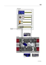
Page 53: ...53 BA023001 en ...
Page 138: ...138 BA023001 en 13 Annex 13 1 Naming convention ...


