


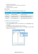


Connecting sensors to the Pulse I/O card
Wiring the Pulse input
Each Pulse I/O card provides one pulse input for connecting devices such as rate pulsing flow meters. The
pulse input terminals available on each Pulse I/O card are shown in the diagram below.
Cable length guidelines
l
Wherever possible sensors should only be grounded at the XCi device end.
l
Long pulse cable input runs require proper grounding and minimisation of ground loops.
l
For sensors powered by +5V, cable lengths <10m are recommended.
l
For sensors powered by +12V, cable lengths <100m are recommended.
Power guidlelines
Because pulse rate sensors are often left running continuously, their power consumption in an important
consideration.
l
A continuously running sensor should have a current consumption
<10mA
.
l
Sensors using
>10mA
require a larger solar panel (eg. 10 Watts).
l
Sensors using
>50mA
should also have an external battery or mains power.
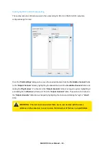
NOTE: Sensors connected to the Pulse I/O card can be configured to switch ON/OFF
to save power rather than run continuously. See
Add a new "Flowrate (using pulse)"
After completing the wiring, configure the sensor using (see
Add a new "Flowrate (using pulse)"
)
MACE XCi User Manual - 96 -
Summary of Contents for HydroMace XCi
Page 1: ......
Page 13: ...MACE XCi User Manual 13...
Page 19: ...MACE XCi User Manual 19...
Page 33: ...MACE XCi User Manual 33...
Page 36: ...MACE XCi User Manual 36...
Page 167: ...NOTE None of these parameters can be edited MACE XCi User Manual 167...
Page 182: ...MACE XCi User Manual 182...
Page 187: ...MACE XCi User Manual 187...
Page 265: ...MACE XCi User Manual 265...